LATEST UPDATES

Wednesday, 20 November 2024

GEOMETRICAL CONSTRUCTIONS

          In this chapter, we deal with problems on Geometrical construction, which are mostly based on plane geometry and which are very essential in the preparation of Engineering Drawings.

They are:

1) Bisecting a Line

2) To draw Perpendiculars

3) To draw Parallel Lines

4) To divide a Line

5) To divide a Circle

6) To Bisect an Angle or Arc

7) To Trisect an Angle

8) To find the centre of an Arc

9) To construct an Ogee (or) Reverse curve

10) To construct Equilateral triangles

11) To construct Squares

12) To construct Regular Polygons

13) Special method of drawing Regular Polygons

14) Regular polygons inscribed in circles

15) To draw regular figures using T-square and set-squares

16) To draw Tangents

17)  Lengths of Arcs

18) Circles and Lines in contact

19) Inscribed Circles.


TO DRAW PARALLEL LINE -- To draw a line through a point and parallel to a given straight line

A) To draw a line through a given point, parallel to a given straight line

1. Let AB be the given line and P be the given point at a distance.

2. With centre P any convenient radius, draw an arc CD cutting AB at E.

3. With the same radius, from point E as centre draw an arc cutting AB at F.

4. Point E as centre and radius equals to FP, draw an arc cutting CD at Q.

5. Draw a line connecting PQ, This is the required line parallel to AB.


B) To draw a line parallel to, and at a given distance from a straight line

1. Let AB be the given line and R is the given radius.

2. Mark points P and Q on line AB, as far apart as convenient.

3. By taking R as radius draw an arc C from given point P.

4. with same radius draw another arc D from point Q.

5. Draw the line CD, just touching the two arc's, now this becomes the parallel line to the given line AB.

Tuesday, 5 November 2024

TO DRAW A PERPENDICULAR TO A GIVEN LINE FROM A POINT OUTSIDE IT (AWAY FROM IT)

 (A) When the point is nearer the centre

(i) Let AB be the line and P be the point.

(ii) With centre P and any convenient radius draw an arc cutting AB at C and D.

(iii) Take any radius greater than half the length of CD in compass, and with centres C and D draw the arcs intersecting each other at E.

(iv) Draw a line connecting P and E, this line cuts the line AB at Q. 

(v) Then PQ is the required perpendicular to AB line.


(B) When the point is nearer to the end of line


(i) Let AB be the line and P be the point.

(ii) With centre A and radius equal to AP, draw an arc cutting AB at C.

(iii) with centre C and radius equal to CP, draw an arc cutting previously drawn arc at D.

(iv)  Draw a line joining P and D and intersecting AB at Q.

(v) then PQ is the required perpendicular.


TO DRAW PERPENDICULARS TO A LINE

  1) To draw a perpendicular to a given line from a point within it.

Method 1:- 

(A) When a point P is near the middle of the line.

(i) Let us consider AB be the given line and P the point on it.

(ii) with P as centre and any convenient radius R1 draw arcs cutting AB at point C and D.

(iii) with any radius R2 greater than R1 and centres C and D, draw arcs intersecting each other at O.

(iv) by using scale draw a line connecting points P and O. Then this is the required perpendicular to the given line.


Method 2:- 

(B) When a point P is near the end of the line.

(i) Let us consider AB be the given line and P the point on it.

(ii) Mark a point O, with O as centre OP as radius, draw an arc greater than the semi-circle cutting AB at C.

(iii) Draw a line joining C and O, and extend it up to arc to cut it at Q,

(iv) Draw the line joining P and Q. Then PQ is the required perpendicular to the given line.


Method 3:- 

(C) When a point P is near the end of the line.

(i) Let us consider AB be the given line and P the point on it.

(ii)  with P as centre and any convenient radius, draw an arc greater than the semi-circle cutting AB at C.

(iii) With the same radius cut the arc into two equal divisions CD and DE.

(iv)  With the same radius drawn an arc from D and cut this arc by drawing same radius arc from E.

(v) Mark this intersecting point as Q. 

(vi) Draw a line joining P and Q, This is the perpendicular to the line AB.

Saturday, 2 November 2024

Representing scale in engineering drawing

          The proportion between the drawing and the object can be represented by two ways as follows: 

a) Scale:- 1cm = 1m (or) 1cm = 100cm (or) 1:100

b) Representative Fraction:- (RF) = 1/100 

"The ratio of the length of the object represented on drawing to the actual length of the object represented is called the Representative Fraction (i.e., RF)".

There are three types of scales depending upon the proportion it indicates as 

1. Full Scale: Some times the actual dimensions of the object will be adopted on the drawing then in that case it is represented by the scale and RF as 

Scale:- 1cm = 1cm (or) 1:1 and by R.F =1/1 (equal to one)

2. Reducing scale: When the dimensions on the drawing are smaller than the actual dimensions of the object. It is represented by the scale and RF as 

Scale:- 1cm = 100cm (or) 1:100 and by R.F=1/100 (Less than one)

3. Enlarging scale: In some cases when the objects are very small like inside parts of a wrist watch, the dimensions adopted on the drawing will be bigger than the actual dimensions of the objects then in that case it is represented by scale and RF as 

Scale:- 10cm = 1cm (or) 10:1 and by R.F =10/1 (Greater than one)


Note: The scale or R.F of a drawing is given usually below the drawing. If the scale adopted is common for all figures under the title of the sheet.


Scales in drawing

          Usually the word scale is used for an instrument used for drawing straight lines, but in Engineering language scale means '' The proportion  (or) ratio between the linear dimensions adopted for the drawing to the actual dimensions of the object". 

It can be indicated in three different ways.

1) For example a 75mm long pencil may be shown by a drawing of 75mm length, drawings drawn of same size of the objects, are called full-size drawings.

2) For example the actual dimensions of the room say 10m X 8m cannot be adopted on the drawing. In suitable proportion the dimensions should be reduced in order to adopt conveniently on the drawing sheet. If the room is represented by a rectangle of 10cm X 8cm size on the drawing sheet that means the actual size is reduced by 100 times. This is called reduced scale.

3) For example if we draw a small size object to an increased size of our convenience, then this is called enlarging scale.


Tuesday, 15 October 2024

PRACTICAL HINTS ON DIMENSIONING

 1) Dimension lines should be drawn at least 8 mm away from the outlines and from each other.

2) Dimensions in a series may be placed in any one of the following two ways:

a) Continuous or Chain dimensioning:

Dimensions are arranged in straight line. An overall dimension is placed outside the small dimension. Least important dimensions is generally omitted.

b) Progressive or parallel dimensioning:

All dimensions are calculated from a common base line. Cumulative error is avoided by this method. This method is preferable compared to other.

3) Smaller dimensions should be placed nearer the view and the larger further away that so that further away so that extension lines do not cross dimension lines. Extension lines may cross each other or the outlines.

4) When a number of parallel dimension lines are to be shown near each other, the dimensions should be stagged.

5) Dimension should be placed where the shape is easily identified.

Wednesday, 2 October 2024

UNIT OF DIMENSION AND GENERAL RULE FOR DIMENSIONING

UNIT OF DIMENSION:

          As far as possible all dimensions should be given in millimeters, omitting the abbreviation mm. Even when it is not convenient to give dimension in millimeters and another unit is used, only the dimension figures are written. But a foot note such as "All dimensions are present in centimeters/meters" is inserted in a prominent place near the title block. The decimal point in a dimension should be quite distinct and written in line with dimension line. A zero must always precedes the decimal point when the dimension is less than unity.

GENERAL RULE FOR DIMENSIONING:

1) Every dimension of a part/segment must be given, but none should be given more than once.

2) Every dimension should be given so completely that further calculation or assumption of any dimension, or direct measurement from the drawing is not necessary.

3) A dimension should be placed on the view where it use is shown more clearly.

4) Dimension should be placed outside the views, unless they are clearer and more easily read inside.

5) Dimensioning between hidden lines and mutual crossing of dimension lines should be avoided. 

6) Dimension lines should not cross any other line of the drawing.

7) An outline or centre line should never be used as a dimension line. A centre line may be extended to serve as an extension line.

8) In general we use two types of dimensional systems (i.e, Unidirectional and aligned), in those Aligned dimensioning system is recommended.


PLACING OF DIMENSIONS

          It is necessary to indicate the size, and other details of the object for the construction and function, using lines, numerals, symbols, notes etc, we indicate the details in a drawing by proper dimensioning. Dimensions are written either above the dimension lines or inserted at the middle by breaking the dimension lines.

Normally dimensions are placed according to either of the following two systems:

1) Aligned System and

2) Unidirectional system

1) Aligned system:

          In Aligned system, the dimension is placed perpendicular to the dimension line in such a way that it may be read from the bottom edge or the right-hand edge of the drawing sheet. The dimension should be placed near the middle and above, clear of the dimension lines.

2) Unidirectional system:

          In unidirectional system, all the dimensions are placed in one direction such that they can be read from the bottom of the drawing. In this system, the dimension lines are broken near the middle for inserting the dimensions. This system is mainly used on large drawings -- as of automobiles etc., where it is inconvenient to read dimensions from the right-hand side.


Saturday, 28 September 2024

TYPES OF LINES

TYPES OF LINES:

1) Out Lines:

          These are the most common lines used in Drawings. Lines drawn to represent visible edges, corners and surface boundaries of objects are called as Outlines (or) Principle lines. They are continues thick and solid lines.

2) Margin Lines:

          These lines are continues thick and wide lines along which the points are trimmed.

3) Dimension Lines and extension Lines:

          Dimension lines are thin, solid lines. These lines show the direction, length, and limits of the dimensions of a part. Dimension lines are drawn with an arrowhead at both ends. They are terminated at the outer ends by pointed arrowheads touching the outlines, extension lines or centre lines. A single style of arrowhead should be used throughout the drawing.

          Extension lines are also continues thin lines. Extension lines are drawn close to, but never touching, the edges or surface they limit. These are extended by  about 3 mm beyond the dimension line, length of extension lines is generally suited to the number of dimensions they limit. They should be perpendicular, or at right angles, to the dimension line. 

4) Construction lines:

          These lines are used for constructing figures. These are shown in geometrical drawings only. These are continues thin light lines.

5) Hatching or section lines:

          Section lines, also known as hatch patterns, indicate the surfaces in a sectional view as they would appear if the part were actually cut along the cutting plane line. These are continues thin lines that are normally drawn at 45-degree angle to the main outline of the section. They are uniformly spaced about 1 mm to 2 mm apart. 

6) Leader (or) Pointer Lines:

          Leader lines is drawn to connect dimensional notes, material specifications, and process notes with the feature to which it applies. It is a continues thin, solid line with an arrowhead at one end. These are bent (or) angled at the start, but should always end horizontal at the notation. When leader lines reference a surface, a dot is used instead of an arrowhead.


7) Border Lines:

          Perfectly rectangular workspace is determined by drawing the border lines. These are continues thin lines.

8) Break Lines:

          Break lines are drawn to show that a part has been shortened to reduce its size on the drawing. In general two variations of break lines in engineering drawing, they are the long break line and the short break lines. 

          Long break lines are thin ruled lines with short zigzags within them to indicate a break.

          Short break lines are continues thick, wavy solid lines that are drawn freehand. They are drawn to show a short break, or irregular boundaries.

          When either of these break lines is used to shorten an object, you can assume that the section removed from the part is identical to the portions shown on either side of the break.

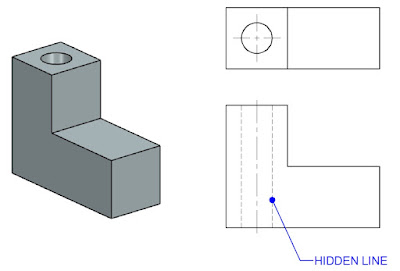
9) Hidden (or) Dotted Lines:

          Hidden lines are used to show edges and surfaces that are not visible in a view. These are also called as Dotted lines. These lines are drawn as thin, evenly spaced dashes ( 2 mm spaced and equal distances of 1 mm apart). A surface or edge that is shown in one view with an object line will be shown in another view with a hidden line. When a hidden line meets or intersects another hidden line or an outline, their point of intersection or meeting should be clearly shown.

10) Centre Lines:

          These lines are drawn to indicate the axes of cylindrical, conical or spherical objects or details, and also used to show the centre lines of circles and arcs. They are thin, long, chain lines  composed of alternatively long and dot spaced approximately 1 mm apart. Centre lines should extend for a short distance beyond the outlines to which they refer. Centre lines can also show the symmetry of an object. The point of intersection of the two centre lines must always be indicated.

11) Cutting plane lines:

          The location of the cutting plane is shown by this line. This is long, thin, chain line, thick at ends only.

12) Chain Thick:

          These lines are used to indicate special treatment of the surface.


Friday, 27 September 2024

LINES in Drawing

Various types of lines used in general engineering drawing are shown below  

Types of Lines:

Solid Lines:

          These are the most commonly used lines in Engineering Drawing. They represent the edges, surfaces, or Outlines of an object, Solid lines are typically used to depict the visible parts of an object.
Thin Lines:

          These are used for various purposes, such as dimension lines (showing the size of an object), Extension lines (extending a line on an object to aid in dimensioning), and leader lines (connecting a dimension number or note to a feature).

Dashed Lines:

Also known as hidden lines. Dashed lines are used to represent edges or surfaces that are not visible in a particular view. For example, they might show the edges of an object that are hidden behind other parts.

Dotted Lines:

          Often used for center lines or symmetry lines, dotted lines indicate the geometric centre of an object or a part. They can also be used to represent the path of movement for moving parts.

Phantom Lines:

          These are used to indicate alternate positions of a moving part or adjacent positions of related parts.

Centre Lines:

          Parts with holes and symmetrical features can be shown by using centre lines. Symmetry can reduce the number of dimensions in a drawing and make it more visually appealing, making it easier for the reader to comprehend.

Dimension Lines:

          Extension lines are used to describe the data being collected. Two arrow heads separate the extension lines on the dimension line from the measurement above (or inside, as shown in the image).

Cutting plane Lines:

          The cutting plane lines illustrate the path of the cutout in a cutout view. The A-A cutting line may be seen here bringing both types of holes into view.


@2017 All Rights Reserved. Designed by WWW.SMARTWAY4STUDY.COM !!!! Sitemap !!!! Blogger Templates