LATEST UPDATES

Tuesday 30 August 2016

EXERCISES - Longitudinal and Transverse Vibrations

EXERCISES


1. What are the causes and effects of vibrations?
2. Define the terms Time period, Cycle and Frequency in Vibrations?
3. Define, in short, free vibrations, damped vibrations and forced vibrations?
4. Discuss briefly with neat sketches the Longitudinal, Transverse and Torsional free vibrations. 
5. Derive an expression for the natural frequency of free transverse and longitudinal vibrations by equilibrium method?
6. Discuss the effect of inertia of the shaft in longitudinal and transverse vibrations.
7. Deduce an expression for the natural frequency of free transverse vibrations for a simply supported shaft carrying uniformly distributed mass of 'm' kg per unit length.
8. Deduce an expression for the natural frequency of free transverse vibrations for a beam fixed at both ends and carrying a uniformly distributed mass of 'm' kg per unit length.
9. Establish an expression for the natural frequency of free transverse vibrations for a simply supported beam carrying a number of point loads, by (a) Energy method; and (b) Dunkerley's method.
10. Explain the term 'whirling speed' or 'critical speed' of a shaft. Prove that the whirling speed for a rotating shaft is the same as the frequency of natural transverse vibration.
11. Derive the differential equation characterizing the motion of an oscillation system subject to viscous damping and no periodic external force. Assuming the solution to the equation, find the frequency of oscillation of the system.
12. Explain the terms 'under damping, critical damping' and 'over damping'
13. Explain the term 'Logarithmic decrement' as applied to damped vibrations 
14. Establish an expression for the amplitude of forced vibrations.
15. Explain the term 'dynamic magnifier'.
16. What do you understated by transmissibility? 

Sunday 28 August 2016

OBJECTIVE QUESTIONS - Longitudinal and Transverse Vibrations

Longitudinal and Transverse Vibrations
Objective type questions

1. When there is a reduction in amplitude over every cycle of vibration, then the body is said to have
(a) Free vibration          (b) Forced vibration          (c) Damped vibration

2. Longitudinal vibrations are said to occur when the particles of a body moves
(a) Perpendicular to axis 
(b) Parallel to its axis 
(c) In a circle about the axis

3. When a body is subjected to transverse vibrations, the stress induced in a body will be
(a) Shear stress          (b) Tensile stress          (c) Compressive stress

4. The factor which affects the critical speed of the shaft is
(a) Diametre of the shaft               (b) Span of the shaft  
(c) Eccentricity                               (d) All of these

5. The ratio of the maximum displacement of the forced vibration to the deflection due to the static force, is known as
(a) Damping factor               (b) Damping coefficient 
(c) Logarithmic decrement  (d) Magnification factor

6. In vibration isolation system, if  ω/ωn is less than Sqare root 2, then for all values of the damping factor, the transmissibility will be 
(a) Less than unity (b) Equal to unity (c) Greater than unity (d) Zero

Where ω = Circular frequency of the system in rad/s, and 
            ωn = Natural circular frequency of vibration of the system in rad/s

7. In vibration isolation system, if ω/ωn is greater than 1, then the phase difference between the transmitted force and the disturbing force is 
(a) 0°           (b)  90°
(c) 180°        (d) 270° 


Friday 19 August 2016

Introduction

          We have already discussed that when the particles of a shaft or disc move in a circle about the axis of a shaft, then the vibrations are known as Torsional vibrations. A shaft is assumed to be weightless and fixed at one end and carrying a heavy disc or flywheel at the free end, can be made to vibrate in a circle about the axis of the shaft by applying an external shaft by applying an external torque on the disc (the external torque is removed after initial displacement). In this case, the shaft is twisted and untwisted alternatively and torsional shear stresses are induced in the shaft. In this chapter, we shall now discuss the frequency of torsional vibrations of various systems such as :
  1. Natural frequency of free Torsional Vibrations.
  2. Effect of Inertia of the constraint on Torsional vibrations.
  3. Free Torsional vibrations of a Single Rotor System.
  4. Free Torsional Vibrations of a Two Rotor System.
  5. Free Torsional Vibrations of a Three Rotor System.
  6. Torsionally Equivalent Shaft
  7. Free Torsional Vibrations of a Geared System.

Natural Frequency of Free Torsional Vibrations

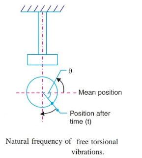
          Consider a shaft of negligible mass whose upper end is fixed and the lower end carries a heavy disc. If the disc is given a twist about its vertical axis and then released, it will start oscillating about the axis, which are known as Torsional vibrations


Let   θ = Angular displacement of the shaft from mean position after time 't' in radians,
             m = Mass of disc in kg,
             I = Mass moment of inertia of disc in kg-m = m.k2,
             k = Radius of gyration in metres,
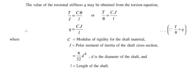
             q = Torsional stiffness of the shaft in N-m.

At any instant, the torque acting on the disc are:
(1) Inertia torque and 
(2) Restoring torque or restoring force (or spring torque)
The inertia torque is equal to accelerating torque but opposite in direction.

Equating equations (iand (ii), the equation of motion is 
The fundamental equation of the simple harmonic motion is
Comparing equations (iiiand (iv)

Note :


Thursday 18 August 2016

Free Torsional Vibrations of a Single Rotor System

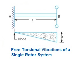
          Fig shows a shaft whose one end is fixed and the other end carries a rotor. This is known a single rotor system. When torsional vibrations are produced in this system, the natural frequency of torsional vibrations of this system is given by

Where                 C = Modulus of rigidity for shaft materials, 
                             J = Polar moment of inertia of shaft,
                             d = Diameter of shaft,
                             L = Length of shaft,
                             m = Mass of the rotor,
                             K = Radius of gyration of rotor, and 
                             I = Mass moment of inertia of rotor =   mK2

          The amplitude of vibration is maximum at free end where single rotor is attached where as the amplitude of vibrations is zero at fixed end of the shaft. This consideration will show that the amplitude of vibration is zero at A and maximum at B, as shown in Fig. It may be noted that the point or the section of the shaft whose amplitude of torsional vibration is zero is known as 'Node'. In other words, at the node, the shaft remains unaffected by the vibration.

Free Torsional Vibrations of a Two Rotor System

          Consider a two rotor system as shown in Fig. (a). It consists of a shaft with two rotors at its ends (free ends). In this system, the torsional vibrations occur only when the two rotors A and B move in opposite directions i.e. If A moves in anticlockwise direction then B moves in clockwise direction at the same instant and viceversa. It may be noted that the two rotors must have the same frequency.
          Also at some point along the shaft, there will be a section of the shaft which remains unaffected by the vibrations. This section is known as 'Node'. We see from Fig. (b). that the node lies at point N. The shaft behaves as if the shaft clamped at node and the two sections vibrate as two separate shafts with the same frequency but opposite in phase or opposite direction. Hence the sections NP and NQ can be considered as two separate shafts fixed at N as shown in Fig. (c) & (d). 

Let       l = Length of shaft,
             lA = Length of part NP i.e. distance of node from rotor A,
             lB = Length of part NQ, i.e. distance of node from rotor B,
             IA = Mass moment of inertia of rotor A,
             IB = Mass moment of inertia of rotor B, d = Diameter of shaft,
             J = Polar moment of inertia of shaft, and
             C = Modulus of rigidity for shaft material.

Natural frequency of torsional vibrations for rotor A, 
and natural frequency of rotor B, 
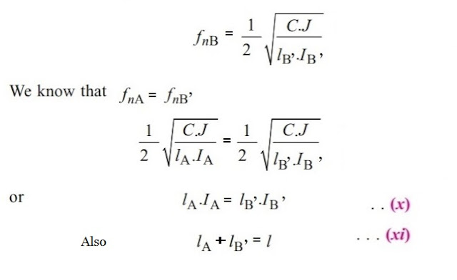
since      fnA = fnB, therefore 
We also know that 
                              l =     l lB

From the equations (iii) and (vi) , we may find the value of and  and hence the position of node. Substituting the values of lA or lB in equations (i) or (ii), the natural frequency of torsional vibration for a two rotor system may be evaluated.

Note : The line eNf in Fig. (b). is known as elastic line for the shaft.

Wednesday 17 August 2016

Free Torsional Vibrations of a Three Rotor System

          Consider a three rotor system as shown is Fig. (a). It consists of a shaft and three rotors A,B and C. The rotors A and C are attached to the free ends of the shaft, whereas the rotor B is attached in between A and C. The torsional vibrations may occur in two ways, that is with either one node or two nodes. In each case, the two rotors rotate in one direction and the third rotor rotates in opposite direction with the same frequency. Let the rotors A and C of the system, as shown in Fig. (a), rotates in the same direction and the rotor B in opposite direction. Let the nodal points or nodes of such a system lies at as shown in Fig. (b). As discussed previously, the shaft may be assumed as a fixed end at the nodes.

Fig.  Free torsional vibrations of a three rotor system.

Let     l1 = Distance between rotors A and B,
           l2 = Distance between rotors B and C,
           lA = Distance of node N1 from rotor A,
           lC = Distance of node N2 from rotor C,
           IA = Mass moment of inertia of rotor A,
           IB = Mass moment of inertia of rotor B,
           IC = Mass moment of inertia of rotor C,
          d = Diameter of shaft,
          J = Polar moment of inertia of shaft, and
          C = Modulus of rigidity for shaft material.

Natural frequency of torsional vibrations of rotor A,  
Natural frequency of torsional vibrations of rotor B, 
and , Natural frequency of torsional vibrations of rotor C, 
Since fnA = fnB = fnC, therefore equating equations (i) and (ii), 
Now equating equations (ii) and (iii),
          On substituting the value of lA from equation (iv) in the above expression, a quadratic equation in lC is obtained. Therefore, there are two values of lC and correspondingly two values of lA. One value of lA and corresponding value of lC gives the position of two nodes. The frequency obtained by substituting the value of lA or lC in equation (i) or (iii) is known as Two node frequency. But in the other pair of value, one gives the position of single node and the other is beyond the physical limits of the equation. In this case, the frequency obtained is known as Fundamental frequency or single node frequency.

Note:

(1). A two rotor system has one natural frequency of vibration.
(2). A three rotor system has two natural frequency.
(3). Hence the number of different natural frequencies of a given system is one less than the number of rotors in the system.
(4). In a three rotor system, for single node of  lA > l1, then node lies between B and C . On the other hand if ll2 , then node lies between A and B.  

Tuesday 16 August 2016

Torsionally Equivalent Shaft

Definition:
          Torsionally equivalent shaft is a shaft of uniform diameter which twists through the same angle as the actual shaft of different diameters and different lengths, when equal and opposite torques of given amount are applied.

          In the previous articles, we have assumed that the shaft is of uniform diameter. But in actual practice, the rotors are fixed to a shaft may have variable diameter for different lengths. To find the frequency of such a system, such a shaft may, theoretically, be replaced by an equivalent shaft of uniform diameter.
          Consider a shaft of varying diameters and varying lengths as shown in Fig. (a). Let this shaft is replaced by an equivalent shaft of uniform diameter 'd' and length 'L' as shown in Fig. (b). These two shafts must have the same total angle of twist when equal opposing torques 'T' are applied at their opposite ends.
Let     d1d2 and d3 = Diameters for the lengths l1, l2 and l3 respectively,
          θ1,  θ2 and θ3 = Angles of twist for the lengths l1, l2 and l3 respectively, 
          θ = Angle of twist for the diameter 'd' and length 'l',
   J1, J2 and J3 = Polar moment of inertia  for the shaft of diameters d1dand drespectively.

We know that torsional equation as

          Since the total angle of twist of the shaft is equal to the sum of the angle of twists of different lengths, therefore

          In actual practice, it is assumed that the diameter 'd' of the equivalent shaft is equal to one of the diameter of the actual shaft. Let us assume d = d1.
This expression gives the length (L) of the Equivalent shaft.


Saturday 13 August 2016

Free Torsional Vibrations of a Geared System

          Consider a geared system as shown in Fig. a. It consists of a driving shaft C which carries a rotor A. It drives a driven shaft D which carries a rotor B, through a pinion E and a gear wheel F. This system may be replaced by an equivalent system of continuous shaft carrying a rotor A at one end and rotor B at the other end, as shown in Fig. b. It is assumed that
  1. The gear teeth are rigid and do not distort under the tooth loads ( are always in contact),
  2. There is no backlash in the gearing, and 
  3. The inertia of the shafts and gears is negligible.

Let       d1 and d2  = Diameters of the shafts C and D respectively,
             l1 and l2 = Lengths of the shafts C and D,
             Iand I= Mass moment of inertia of the rotors A and B, 
             ωand ωB = Angular speed of the rotors A and B,
            d = Diameter of the equivalent shaft, 
            l = Length of the equivalent shaft, and 
           IB = Mass moment of the inertia of the equivalent rotor B’.

          If the shafts are not strained beyond the limit of proportionality, each rotor in the geared system will oscillate with simple harmonic motion and there will be a node either in length l1 or in the length l2 .
The following two conditions must be satisfied by an equivalent system:
  1. The kinetic energy of the equivalent system must be equal to the kinetic energy of the original system.
  2. The maximum strain energy of the equivalent system must be equal to the maximum strain energy of the original system.
In order to satisfy the condition (1) for a given load,
K.E. of section l1 + K.E. of section l= K.E. of section l1 + K. E. of section l2 
                    K.E. of section l3 = K.E. of section l2

In order to satisfy the condition (2)  for a given shaft diameter, 
                Strain energy of  land l3 = Strain energy of  l1 and l
                   Strain  energy of l3 = Strain energy of l2 


Where   T2 and T3 = Torque on the sections l2 and l3, and
             θ2 and θ3 = Angle of twist on sections l2 and l3.
Assuming that the power transmitted in the sections l3 and l2 is same, therefore, 

          Thus the single shaft is equivalent to the original geared system, if the mass moment of inertia of the rotor B satisfies the equation (i) and the additional length of the equivalent shaft l3 satisfies the equation (viii).
Length of the equivalent shaft, 
          Now the natural frequency of the torsional vibration of a geared system (two rotor system) may be determined as discussed below:
          Let the node of the equivalent system lies at N as shown in Fig. c. then the natural frequency of torsional vibration of rotor A, 
and natural frequency of the torsional vibration of rotor B,
          From the equations (x) and (xi), the value of and may be obtained and hence the natural frequency of the torsional vibrations is evaluated.


@2017 All Rights Reserved. Designed by WWW.SMARTWAY4STUDY.COM !!!! Sitemap !!!! Blogger Templates