LATEST UPDATES

Tuesday 14 March 2017

Variation of Tractive Force

The tractive force is the reasultant unbalanced force due to the twi cylinders along the line of stroke. The unbalanced portion of the primary force which along the line of stroke causes the variation in the tractive force or effect. Let C is the friction of reciprocating masses that is balanced. Let the crank for the first cylinder be inclined at an angle Î¸ with the line of stroke, as shown in Fig., Since the crank for the second cylinder is at right angle to the first crank, therefore the angle of inclination for the second crank will be (90° + θ).

Let        m  = Mass of the reciprocating parts per cylinder, and 
              C   = Fraction of the reciprocating parts to be balanced.

        We know that unbalanced force along the line of stroke for cylinder 1, 
         Similarly, unbalanced force along the line of stroke for cylinder 2,
As per defination the tractive force,
                         FT = Resultant unbalanced force along the line of stroke, 
The tractive force is maximum or minimum when (cos Î¸ - sin Î¸)  is maximum or minimum.
For (cos θ - sin θ) to be maximum or minimum.
Maximum or minimum value of tractive force or the variation of tractive force is


Thursday 9 March 2017

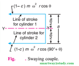
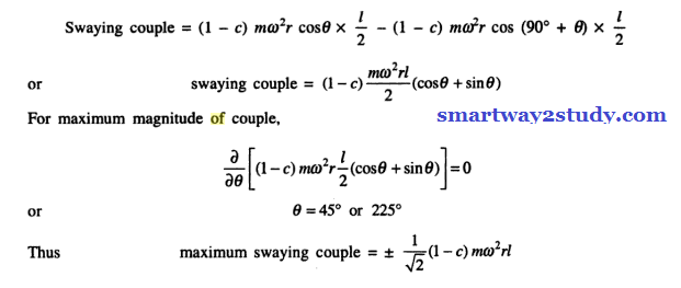
Swaying couple


2. Swaying couple:


        The unbalanced portions of forces acting along the line of stroke are distance 'l' apart. These forces constitutes a couple about YY axis, which tends to make the leading wheels sway from side to side. This couple is known as swaying couple.

Note: In order to reduce the magnitude of the swaying couple, revolving balancing masses are introduced. But, as discussed in the previous article, the revolving balancing masses cause unbalanced forces to act at right angles to the line of stroke. These forces vary the downward pressure of the wheels on the rails and cause oscillation of the locomotive in a vertical plane about a horizontal axis. Since a swaying couple is more harmful than an oscillating couple, therefore a value of 'C' from 2/3 to 3/4, in two-cylinder locomotive with two pairs of coupled wheels, is usually used. But in large four cylinder locomotives with three or more pairs of coupled wheels, the value of 'C' is taken as 2/5.

Wednesday 8 March 2017

Hammer Blow


3. Hammer Blow:

          The maximum magnitude of unbalanced force acting perpendicular to the line of stroke is called Hammer Blow. At high speed, this unbalanced force tries to lift the wheels from the rail. 
Let W be the dead weight of the wheel. We know that the unbalanced force along the perpendicular to the line of stroke due to the balancing mass 'm', at a radios 'r' in order to balance reciprocating parts only is mω2r sin Î¸.  This force is maximum when the value of the unbalanced force is equal to mω2(when sin Î¸ is unity, i.e. Î¸ = 90° or 270° ). 
Thus the threshold condition for lifting of wheel (Hammer blow) can be written as 
                             Hammer Blow  ( W )   =  mω2

The effect of hammer blow is to cause the variation in pressure between the wheel and the rail. This variation is shown in Fig., for one revolution of the wheel. 
Let P be the downward pressure on the rail (or static wheel load)

∴ Net pressure between the wheel and the rail 
P ± mω2
If  (P - mω2r )  is negative, then the wheel will be lifted from the rails. Therefore the limiting condition in order that the wheel does not lift from the rails is given by 
                                               P = mω2r    
and permissible value of angular speed  (or) lifting angular velocity of the crank :


Balancing of Coupled Locomotives


          In a coupled locomotive, the driving wheels are connected to the leading and trailing wheels by an outside coupling rod. By such an arrangement, a greater portion of the engine mass is utilised by tractive purposes. In coupled locomotives, the coupling rod cranks are placed diametrically opposite to the adjacent main cranks (i.e. Driving cranks). The coupling rods together with cranks and pins may be treated as rotating masses and completely balanced by masses in the respective wheels. Thus in a coupled engine, the rotating and reciprocating masses must be treated separately and the balanced masses for the two systems are suitably combined in the wheel.
          It may be noted that the variation of pressure between the wheel and the rail (i.e. Hammer blow) may be reduced by equal distribution of balanced mass between the driving , leading and trailing wheels respectively.

Balancing of Primary Forces of Multi-cylinder In-line Engines

          The multi-cylinder engines with the cylinder centre lines in the same plane and on the same side of the centre line of the crankshaft, are known as In-line engines.
          The following two conditions must be satisfied in order to give the primary balance of the reciprocating parts of a multi-cylinder engine:

1. The algebraic sum of the primary forces must be equal to zero. In other words, the primary force polygon must be close; and 
2. The algebraic sum of the couples about any point in the plane of the primary forces must be equal to zero. In other words, the primary couple polygon must close.

We have already discussed, that the primary unbalanced force due to the reciprocating masses is equal to the component, parallel to the line of stroke, of the centrifugal force produced by the equal mass placed at the crank pin and revolving with it. Therefore, inorder to give the Primary balance of the reciprocating parts of a multi-cylinder engine, it is convenient to imagine the reciprocating masses to be transferred to their respective crank pins and to treat the problems as one of revolving masses.

Notes:

1. For a two cylinder engine with cranks at 180°, condition (1) may be satisfied, but this will result in an unbalanced couple. Thus the above method of primary balancing cannot be applied in this case. 
2. For a three cylinder engine with crank at 120° and if the reciprocating masses per cylinder are same, then condition (1) will be satisfied because the forces may be represented by the sides of an equilateral triangle. However, by taking a reference plane through one of the cylinder centre lines, two couples with non-parallel axes will remain and these cannot wanish vectorically. Hence the above method of balancing fails in this case also. 
3. For a four cylinder engine, similar reasoning will show that complete primary balance is possible and it follows that   'For a multi-cylinder engine, the primary forces may be completely balanced by suitably arranging the crank angles, provided that the number of cranks are not less than four'. 

Balancing of Secondary Forces of Multi-cylinder In-line Engines

          When the connecting rod is not long (i.e. when the obliquity of the connecting rod is considered), then the secondary distributing force due to the reciprocating mass arises.
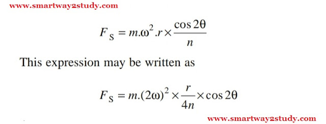
We have discussed in previous articles, that the secondary force,
          As in case of primary forces, the secondary forces may be considered to be equivalent to the component, parallel to the line of stroke, of the centrifugal force produced by an equal mass placed at the imaginary crank of length r/4n and revolving at twice the speed of the actual crank (i.e. 2ω )  as shown in fig.,
          Thus in multi-cylinder in-line engines, each imaginary secondary crank with a mass attached to the crank pin is inclined to the line of stroke at twice the angle of the actual crank. The values of the secondary forces and couples may be obtained by considering the revolving mass. This is done in the similar way as discussed for primary forces. The following two conditions must be satisfied in order to give a complete secondary balance of an engine:
1. The algebraic sum of the secondary forces must be equal to zero. In other words, the secondary force polygon must close, and
2.   The algebraic sum of the couples about any point in the plane of the secondary forces must be equal to zero. In other words, the secondary couple polygon must close.

Note: The closing side of the polygon gives the maximum unbalanced secondary force and the closing side of the secondary couple polygon gives the maximum unbalanced secondary couple.

Tuesday 7 March 2017

Balancing of Radial Engines (Direct and Reverse Cranks Method )

          The direct and reverse crank balancing method (also known as Contra-rotating mass balancing) aren't separate methods but rather one way of modelling the inertial effects of a reciprocating mass. The method of direct and reverse cranks is used in balancing of radial or V-Engines, in which the connecting rods are connected to a common crank. Since the plane of rotation of the various crank (in radial or V-Engines) is same, therefore there is no unbalanced primary or secondary couple. This is convenient for machines that have unaligned stroke centerlines (such as V-Engines and Rotary engines) since it eliminates the need to use "complicated Trigonometry".
          Consider a reciprocating engine mechanism as shown in above Fig (a)., Let the crank OC (known as the direct crank) rotates uniformly at 'ω' radians per second in a clockwise direction. Let at any instant the crank makes an angle 'θ'  with the line of stroke OP. The indirect or reverse crank OC' is the image of the direct crank OC, when seen through the mirror placed at the line of stroke. A little consideration will show that when the direct crank revolves in a clockwise direction, the reverse crank will revolve in the anticlockwise direction. We shall now discuss the primary and secondary forces due to the mass (m) of the reciprocating parts at P.

Considering Primary Forces
          We have already discussed that primary force is m.ω 2.r cosθ . This force is equal to the component of the centrifugal force along the line of stroke, produced by a mass (m) placed at the crank pin C. Now let us support that the mass (m) of the reciprocating parts is divided into two parts, each equal to m/2 . 

          It is assumed that m/2 is fixed at the Direct Crank (termed as primary direct crank) pin C and m/2 at the Reverse crank (termed as primary reverse crank) pin C' , as shown in Fig (b).,
Hence, for primary effects of the mass m of the reciprocating parts at P may be replaced by two masses at C each of magnitude m/2.

Note:   The component of the centrifugal forces of the direct and reverse cranks, in a direction perpendicular to the stroke, are each equal to (m/2).ω 2.r sinθ, but opposite in direction. are balanced.

Considering Secondary Forces:
          We know that the secondary force
         In the similar way as discussed above, it will be seen that for the secondary effects, the mass (m) of the reciprocating parts may be replaced by two masses (each m/2 placed at D and D' such that OD=OD'= r/4n. The crank OD is the secondary direct crank and rotates at 2 rad/s in the clockwise direction, while the crank OD' is the secondary reverse crank and rotates at 2 rad/s in the anticlockwise direction as shown in Fig (c).

Balancing of V-engines

Consider a symmetrical two cylinder V-Engine as shown in Fig., The common crank OC is driven by two connecting rods PC and QC. The lines of stroke OP and OQ are inclined to the vertical OY, at an angle Î± as shown in Fig.,

Let                          m= Mass of reciprocating parts per cylinder,
                                l = Length of connecting rod, 
                                r = Radius of crank,
                                n= Ratio of length of connecting rod to crank radius = l/r
                                θ = Inclination of crank to the vertical at any instant,
                                ω  = Angular velocity of crank.

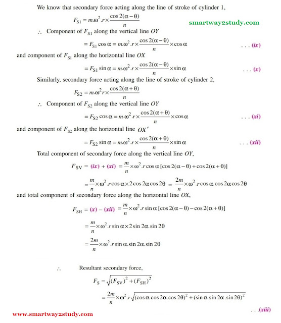
We know that inertia force due to reciprocating parts of the cylinder 1, along the line of stroke, 
and the inertia force due to reciprocating parts of the cylinder 2, along the line of stroke,

The balancing of V-Engines is only considered for primary and secondary forces as discussed below:

Considering primary forces:


Considering secondary forces:

Friday 3 March 2017

EXERCISES - Balancing Of Reciprocating masses

EXERCISES


1. Define Balancing? Write a short note on primary and secondary balancing?
2. Explain why only a part of the unbalanced force due to reciprocating masses is balanced by revolving mass.
3. Derive the following expressions, for an uncoupled two-cylinder locomotive engine:
(a) variation is tractive force  (b) Swaying couple; and (c) Hammer blow
4. Explain the method of balancing a number of masses rotating in one plane by another mass rotating in the same plane
5. What are in-line engines? How are they balanced? It is possible to balance them completely? 
6. Explain the 'direct and reverse crank' method for determining unbalanced forces in radial engines.
7. Discuss the balancing of V-Engines.
8Explain the method of balancing a single rotating mass by another mass in same plane.
9. Five masses A,B,C,D and E Rotate in the same plane at equal radii. The masses A, B and C are 10 kg, 5 kg, and 8 kg respectively. The angular position of masses B, C, D and E measured in the same direction from A are 60°,  135°, 210° and 270° respectively. Find the masses D and E for complete balance.


For ANSWERS CLICK HERE

EXERCISES -SOLUTIONS - Balancing Of Reciprocating masses

Question.5. Explain the method of balancing a single rotating mass by another rotating mass in same plane.

Answer.
When a certain mass is connected to a rotating shaft, it will exert some centrifugal force. The tendency of this centrifugal force is to bend the shaft and to produce vibrations in it. To prevent the effect of the unbalanced centrifugal force, another mass is connected to the opposite side of the shaft at such a position so that the effect of the centrifugal force due to first mass can be balanced.
Fig. Balancing of a Single Rotating Mass by Another Rotating Mass in the Same Plane
Let us consider a mass connected to a shaft as shown in the Fig.
Let


The force acts radially outwards and continuously changes its direction. To counteract this force, a balance mass is introduced at a distance from the axis of the shaft in the same plane of the disturbing force such that centrifugal force of the two masses are equal and opposite.
Letbe the centrifugal force due to balance mass.
For complete balance,
 The product may be split in any convenient way. Normally, is kept large to reduce .

Question.6. Explain the method of balancing a number of masses rotating in one plane by another mass rotating in the same plane.

Answer.
Let us consider four masses attached rigidly to the shaft rotating at angular speed  as shown in Fig. (a). 
Let  are the distances of from the axis of rotating shaft. are the angles of masses  with the X-axis.
The centrifugal force for each mass is proportional to the product of mass and its radius of rotation as  is same for each mass. All these forces are acting radially outwards and form a system of concurrent coplanar forces at point O i.e. on the axis of rotation. The resultant of all such forces can be found by the following two methods:
1. Analytical method,
2. Graphical Method.


(a) Space Diagram                                                                                                  (b) Vector Diagram
Fig. Balancing of a Number of Masses Rotating in One Plane by Another Mass Rotating in the Same Plane
1.            Analytical method :
(i) Resolve each force horizontally and vertically.
(ii) Find the resultant horizontal component () of the centrifugal forces which is
(iii) Similarly, find the resultant vertical () of the centrifugal forces which is
(iv) Find the magnitude of the resultant centrifugal force.
(v) Find the direction of the resultant centrifugal force.
Where is the angle made by the resultant force with X-axis.
(vi) The balancing and the resultant forces are equal and opposite to each other.
(vii) Find the magnitude of the balancing mass from the relation,

2. Graphical Method : The analytical method is lengthy procedure and also there is possibility of mistake in the calculations. Therefore, graphical is generally preferred. The steps followed in the graphical method are as follows:
(i) Draw the space diagram as shown in fig. (a).
(ii) Draw the vector diagram as shown in fig. (b) in such a way that ‘ab’ represents the centrifugal force due to mass which is equal to. Magnitude and direction is drawn on some suitable scale. Similarly bc, cd and de are drawn to represent centrifugal forces due to masses.
(iii) The resultant force is shown by the closing side ‘ae'(dotted line).
(iv) The balancing force is equal and opposite to the resultant force.
(v) Find the magnitude of the balancing mass m such that
 

Question.7. Explain the method of balancing a number of masses rotating in different planes.

Answer.
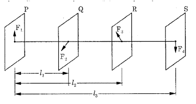
Let us consider four masses  rotating in four different planes at different radii  respectively as shown in fig. Let us consider that all the above four masses are attached to a single rotor rotating with angular velocity . Let the distance of planes from the plane are  respectively.

Fig. Balancing of a Number of Masses Rotating in Different Planes
Let us consider the plane P as reference plane. Now, if we transfer the masses  rotating in planes  to the reference plane , then there will occur four unbalanced forcesand three unbalanced couples  in the reference plane. For complete balancing of the system, the following two conditions must be satisfied:

It should be noted that the distances of planes to the left side of reference plane are taken as negative, while to the right side as positive.

Question.8. Five masses A,B,C,D and E rotate in the same plane at equal radii. The masses A, B and C are 10 kg, 5 kg, and 8 kg respectively. The angular position of masses B, C, D and E measured in the same direction from A are 
respectively. Find the masses D and E for complete balance.

Answer.
Graphical Method:

Component
Mass(m) (kg)
Radius(r)(m)
mr(kgm)
A
10
r
10r
B
5
r
5r
C
8
r
8r
D
E
 mdr
mcr
r
r
 mcr
mcr

From the tabular data and statement of the problem, it is clear that the system is in complete balance. Therefore, the force polygon should be a closed one. Hence it is drawn with the help of data in column 4 of the table as under: 
1. Draw a line parallel to and equal to  or some suitable scale.
2. From point a , draw line ab parallel to OB and equal to 5r.
3. Similarly, draw line bc parallel to OC and equal to 8r.
4 From point c, draw line cd parallel to OD.
5. From point O, draw line ed parallel to OE to cut line cd at point d.
6. Measure cd and equate it to mdr to find the value of md.
7. Similarly, measure de and equate it to mer . Find the value of me .

Let us now solve the above problem by analytical method.
Analytical Method: {see fig. a}
Component
Mass (m)(kg)
Radius (r) (m)
mr (kg m)
mr sin θ
A
0
r10r10r
0
B
5
r5r2.5r4.33
C
8
r8r-5.657r5.657r
Dmdrmdr-0.8666mdr-0.5
Emermer
0
-mer

For complete balance,


From equation (i),

From equation (ii),


@2017 All Rights Reserved. Designed by WWW.SMARTWAY4STUDY.COM !!!! Sitemap !!!! Blogger Templates