LATEST UPDATES

Wednesday 9 October 2019

Types of Pattern

(i) Solid (or) single piece pattern:
          Patterns are made in one piece without joints, partings (or) loose pieces is known as "Single piece pattern" and these are suitable only for very simple castings. There is no provision for Runners and Risers etc., Moulding can be done either in the foundry floor (Called Pit Moulding) or in a Moulding Box. There is no difficulty in withdrawing the pattern from the mould as the broadest portion of the pattern is at the top. As an example, if a cylindrical pin with a circular head has to be cast, a one piece pattern shown in Fig., will be adequate.
(iiSplit pattern
It is not practical to have one piece  


It is not practical to have one piece pattern for parts of complicated shapes, because it would not be possible to withdraw the pattern from the mould. For example, if a circular head was added to the bottom of the pin shown in Fig. 6.1, it would make it necessary to go in for a split pattern as shown in Fig. 6.2.

TYPES OF PATTERN

          Patterns are replicas of the casting required. These are similar in size and shape of the pattern we have to prepare, but not exactly. which are prepared with suitable material and these are used for preparing mould cavity.

          The type pattern to be used for a particular casting depends upon many factors like design of casting, complexity of shape of product, number of castings to be prepared, surface finish and accuracy. The different types of pattern are given below:
(i) Solid (or) Single piece pattern
(ii) Split pattern 
(iii) Loose piece pattern (or) Multi-piece pattern
(iv) Match plate Pattern
(v) Sweep pattern
(vi) Gated pattern
(vii) Skeleton Pattren

PATTERNS IN CASTING

          Patterns are the replicas of the casting required. These are similar in shape and size to the final product to be prepared, but not exactly. Which is prepared with suitable materials and these patterns are used for making mould cavity. Usually, the mould is prepared in wet sand, to which some binder is added to hold sand particles together. The pattern is then withdrawn from inside the sand mould in such a manner that the impression/cavity made in the mould is not damaged or broken in anyway. Finally molten metal is poured into this cavity and allowed to solidify and cool down to room temperature, it forms reproduction of the pattern which is known as 'Casting'.

The requirements of a good pattern are :
1) Secure the desired shape and size of the casting.
2) Pattern should be cheap and readily available.
3) Patterns should be simple in design for ease of manufacturing.
4) They should be light in mass and convenient to handle.
5) Have high strength and long life in order to make as many moulds as required.
6) Retain it's dimensions and rigidity during the definite service life.
7) It's surface should be smooth and wear resistant.
8) Able to with stand rough handling.


CASTING PROCESS

          Casting is one of the oldest manufacturing process. Manufacturing of a machine part by heating a metal (or) alloy above it's melting point and pouring the liquid metal/alloy in a cavity approximately of same shape and size as the machine part required is called as "Casting Process". After leaving some time the liquid metal cools and solidifies, it acquires the shape and size of the cavity and resembles the finished product required. The department of the workshop, where the castings are made is called as "Foundry".

The manufacturing of casting requires the following steps:
a) Preparation of a pattern,
b) Preparation of a mould with the help of the pattern, 
c) Melting of metal or alloy in a furnace,
d) Pouring the liquid metal into the mould cavity,
e) Breaking the mould to retrieve the casting,
f) Cleaning the casting and cutting off risers, runners, etc., (This operation is called 'Fettling'), and 
g) Inspection of casting for any flaws.

          Castings are prepared with a large number of metals and alloys, both ferrous and non-ferrous. Grey cast Iron components are very common; Steel castings are stronger and are used for components subjected to higher stresses. Bronze and Brass castings are used on ships and in marine environment, where Ferrous items will be subjected to heavy corrosion. Aluminium and Aluminium-Magnesium castings are used in automobiles. Stainless steel castings are used for making Cutlery items.
          Castings is an economical way of producing components of required shape either in small lots (or) in large lots. However, castings are less strong as compared to wrought components produced by processes such as forging etc., However castings offer the possibility of having slightly improved properties in certain part of the castings by techniques such as use of chill etc., In casting process, very little metal is wasted.

Balancing of a Single Rotating Mass By Two Masses Rotating in Different Planes

          In the previous article we have discussed that by introducing a single balancing mass in the same plane of rotation as that of disturbing mass, the centrifugal forces are balanced. These two forces are equal in magnitude and opposite in direction. but this type of arrangement for balancing gives rise to a couple which tends to rock the shaft in its bearing. Therefore in order to put the system in complete balance, two balancing masses are placed in two different planes, parallel to the plane of rotation of the disturbing mass, in such a way that they satisfy the following two conditions of equilibrium. 
1. The net dynamic force acting on the shaft is equal to zero. This requires that the line of action of three centrifugal forces must be the same. In other words the centre of the masses of the system must lie on the axis of rotation. This is the condition for Static Balancing.
2. The net couple due to the dynamic forces acting on the shaft equal to zero. In other words, the algebraic sum of the moments about any point in the plane must be zero.
          The above conditions (1) and (2) together gives Dynamic Balancing. The following two possibilities may arise while attaching the two balancing masses:
1. The plane of the disturbing mass may be in between the planes of the two balancing masses, and
2. The plane of the disturbing mass may lie on the left or right of the two planes containing the balancing masses.

We shall now discuss both the above cases one by one.

1. When the plane of the disturbing mass lies in between the planes of the two balancing masses:

          Consider a disturbing mass 'm' lying in a plane 'A' to be balanced by two rotating masses m1 and mlying in two different planes 'L' and 'M' as shown in Fig., Let r, r1 and rbe the radii of rotation of the masses in planes A, L and M respectively.
           Let        l1 = Distance between the planes A and L,
                         l2 =  Distance between the planes A and M, and
                         l Distance between the planes L and M.
     We know that the centrifugal force exerted by the mass 'm' in the plane 'A',
                                   FC = m . r . ω2
     Similarly, the centrifugal force exerted by the mass 'm1' in the plane 'L',
                                   FC 1 = m1 . r1 . ω2
     and, the centrifugal force exerted by the mass 'm2' in the plane 'M', 
                                   FC2 = m2 . r2 . ω2
          Since the net force acting on the shaft must be equal to zero, therefore the centrifugal force on the disturbing mass must be equal to the sum of the centrifugal forces on the balancing masses, therefore
                                                FC = FC 1 + FC2
                                             m . r = m1 . r1 + m2 . r2      ..... (1)
          Now in order to find the magnitude of balancing force in the plane 'L', take moments about 'P' which is the point of intersection of the plane 'M' and the axis of rotation. Therefore
                                               FC 1 X l = FC X l2
                                             m1 . r1 . l = m . r . l2             ...... (2)
          Similarly, in order to find the balancing force in plane 'M', take moments about 'Q' which is the point of intersection of the plane 'L' and the axis of rotation. Therefore
                                               FC2 X l = FC X l1
                                           m2 . r2 . l = m . r . l1              ........ (3)
The equation (1) represents the condition for static balance, but in order to achieve dynamic balancing, equations (2) and (3) must also be satisfied.

2. When the plane of the disturbing mass lies on one end of the planes of the balancing masses:

          In this case, the mass 'm' lies in the plane 'A' and the balancing masses lie in the planes 'L' and 'M', as shown in Fig., As discussed above, the following conditions must be satisfied in order to balance the system, i.e., 
                                              FC + FC2 = FC 1 + FC2
                                     m . r + m2 . r2 = m1 . r1 + m2 . r2        ..... (4)
          Now, to find the balancing force in the plane 'L', take moments about 'P' which is the point of intersection of the plane 'M' and the axis of rotation. Therefore
                                               FC 1 X l = FC X l2
                                             m1 . r. l = m . r . l2             ...... (5)
          Similarly, to find the balancing force in the plane 'M', take moments about 'Q' which is the point of intersection of the plane 'L' and the axis of rotation. Therefore
                                               FC2 X l = FC X l1
                                           m2 . r. l = m . r . l1              ........ (6)


Balancing Of Several Rotating Masses In The Single plane

          Let us Consider four masses of magnitude m1, m2, m3 and mare at a distance of r1, r2, r3 and rfrom the axis of rotating shaft. Let Î¸1, θ2, θ3 and θbe the angles of these masses with the horizontal line OX, as shown in Fig., Consider these masses rotate with a constant velocity of 'ω' rad/sec, about an axis through 'O' and perpendicular to the plane of paper.

          The magnitude and position of the balancing mass may be found out by using two methods, they are analytical method and graphical method. These methods are discussed below:

1. Analytical Method:
1. First we have to find out centrifugal force exerted by each mass on the rotating shaft.
2. We have to resolve the centrifugal forces horizontally and vertically, and find their sums, i.e., Î£H and Î£V. We know that 

Sum of horizontal components of the centrifugal forces, 
                      ΣH = m1 . r1. Cos θ1 + m2 . r2. Cos θ2  ………
and sum of vertical components of the centrifugal forces, 
                      ΣV = m1 . r1. Sin θ1 + m2 . r2. Sin θ2  ………
3. Magnitude of the resultant centrifugal force, 
4. If is the angle, which the resultant force makes with the horizontal, then 
5. The balancing force is then equal to the resultant force, but in opposite direction
6. Magnitude of balancing mass, such that 
                         Fc = m . r
       Where     m = Balancing Mass, 
                        r   =  It's radius of rotation

2. Graphical Method:
1. Draw space diagram of several masses based on their positions as shown in above Fig., 
2. We have to find out centrifugal force exerted by each mass on the rotating shaft.
3. Now draw the vector diagram with the centrifugal forces we obtained.
4. Here 'ab' represents the centrifugal force exerted by the mass m1 (i.e., m1 . r1 ) in magnitude and direction to some suitable scale. 
5. Similarly for other masses m2, m3 and m4, draw 'bc', 'cd', and 'de'.
5. The balancing force is then equal to the resultant force, but in opposite direction
6. Magnitude of balancing mass (m) at a given radius of rotation (r), such that 
                         Fc = m . ω2. r = Resultant centrifugal force
                                          m . r = Resultant of  m1 . r1 , m2 . r2 , m3 . r3 , m4 . r4

Tuesday 8 October 2019

Balancing of Several Masses Rotating in Different Planes

When several masses revolve in different planes, they can be transferred to a 'Reference plane' (R.P), which may be defined as the plane passing through a point on the axis of rotation and perpendicular to it. The effect of transferring a revolving mass (in one plane) to a reference plane is to cause a force of magnitude equals to the centrifugal force of the revolving mass to act in the reference plane, together with a couple of magnitude equal to the product of the force and the distance between the plane of rotation and the reference plane. In order to have a complete balance of the several revolving masses in different planes, the following conditions must be satisfied:
1. The resultant force must be zero (i.e All the forces in the reference plane must be balanced)
2. The resultant couple must be zero (i.e The couple about the reference plane must be balanced)
Let us now consider four masses revolving in different planes 1, 2, 3 and 4 respectively as shown in Fig., (a), and their relative angular positions are shown in Fig (b).,

          The magnitude of the balancing masses mand min planes A and B may be obtained as discussed below.
1. Take one of the plane say A, as reference plane (R.P).
2. The distances of the other planes to the left of the reference plane is taken as negative, and those are present on the right as Positive.
3. Tabulate the planes data in the same order from left to right as shown in below table.

4. A couple may be represented by a vector drawn perpendicular to the plane of couple. Couple C1 is obtained by transferring mto the reference plane through O. The couple obtained is m1 . r1 . land it acts in a plane through and perpendicular to the paper. The vector representing this couple is drawn in the plane of the paper and perpendicular to Omas OCshown by in Fig., Similarly the remaining vectors for remaining masses is calculated and shown in Fig.,
5. The couple vectors as discussed above, are turned counter clockwise through a right angle for convenience of drawing without changing relative positions.
6. Now draw the couple polygon as shown in Fig., The couples about the reference plane must be balance. i.e., the resultant couple must be zero.

7. Now draw the force polygon as shown in Fig., The forces in the reference plane must balance. i.e., the resultant forces must be zero.

From the above expression, the value of balancing mass min the plane 'A' may be obtained and the angle of inclination of this mass with the horizontal may be measured from Fig., (Angular positions of masses


Monday 7 October 2019

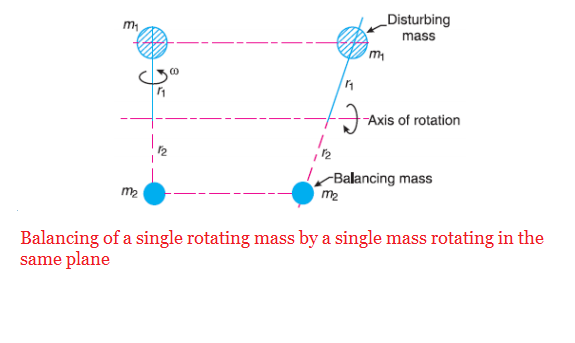
Balancing of a Single Rotating Mass By a Single Mass Rotating in the Same Plane

          Let us consider a disturbing mass (Extra mass) 'm1' attached to a shaft rotating at 'w rad/s as shown in Fig.,. Imagine, that mass 'm1' is rotating at a distance  'r1' (radius of rotation) (i.e., distance between the axis of rotation of the shaft and the centre of gravity of the mass).
We know that the centrifugal force exerted by any mass on the shaft,
                                  FC = m .w2. r
Then centrifugal force exerted by the mass 'm1' is 
                                 FC1 = m1 .w2. r1         . . . . . (i)
          We all know that centrifugal force always acts radially outwards and thus this centrifugal force produces bending moment on the shaft. In order to counteract the effect of this force, a balancing mass 'm2' may be attached in the same plane of rotation as that of disturbing mass 'm1' such that the centrifugal forces due to the two masses are equal and opposite.
Let r2= Radius of rotation of mass 
Centrifugal force due to mass 'm2',
                                 FC2 = m.w2. r2         . . . . . (ii)
Equating equations (iand (ii)
                                m.w2. r1 = m.w2. r2
                                                  (or)
                                       m. r1 = m. r2

Note: 1. The centrifugal forces are proportional to the product of the masses and radius of rotation of respective masses, because 'w2 ' is same for each mass.
2.   


@2017 All Rights Reserved. Designed by WWW.SMARTWAY4STUDY.COM !!!! Sitemap !!!! Blogger Templates