LATEST UPDATES
Showing posts with label Balancing of Rotating Masses. Show all posts

Tuesday, 8 October 2019

Balancing of Several Masses Rotating in Different Planes

When several masses revolve in different planes, they can be transferred to a 'Reference plane' (R.P), which may be defined as the plane passing through a point on the axis of rotation and perpendicular to it. The effect of transferring a revolving mass (in one plane) to a reference plane is to cause a force of magnitude equals to the centrifugal force of the revolving mass to act in the reference plane, together with a couple of magnitude equal to the product of the force and the distance between the plane of rotation and the reference plane. In order to have a complete balance of the several revolving masses in different planes, the following conditions must be satisfied:
1. The resultant force must be zero (i.e All the forces in the reference plane must be balanced)
2. The resultant couple must be zero (i.e The couple about the reference plane must be balanced)
Let us now consider four masses revolving in different planes 1, 2, 3 and 4 respectively as shown in Fig., (a), and their relative angular positions are shown in Fig (b).,

          The magnitude of the balancing masses mA and mB in planes A and B may be obtained as discussed below.
1. Take one of the plane say A, as reference plane (R.P).
2. The distances of the other planes to the left of the reference plane is taken as negative, and those are present on the right as Positive.
3. Tabulate the planes data in the same order from left to right as shown in below table.

4. A couple may be represented by a vector drawn perpendicular to the plane of couple. Couple C1 is obtained by transferring m1 to the reference plane through O. The couple obtained is m1 . r1 . l1 and it acts in a plane through and perpendicular to the paper. The vector representing this couple is drawn in the plane of the paper and perpendicular to Om1 as OC1 shown by in Fig., Similarly the remaining vectors for remaining masses is calculated and shown in Fig.,
5. The couple vectors as discussed above, are turned counter clockwise through a right angle for convenience of drawing without changing relative positions.
6. Now draw the couple polygon as shown in Fig., The couples about the reference plane must be balance. i.e., the resultant couple must be zero.

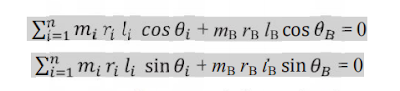
7. Now draw the force polygon as shown in Fig., The forces in the reference plane must balance. i.e., the resultant forces must be zero.

From the above expression, the value of balancing mass mA in the plane 'A' may be obtained and the angle of inclination of this mass with the horizontal may be measured from Fig., (Angular positions of masses) 


Monday, 7 October 2019

Balancing of a Single Rotating Mass By a Single Mass Rotating in the Same Plane

          Let us consider a disturbing mass (Extra mass) 'm1' attached to a shaft rotating at 'w rad/s as shown in Fig.,. Imagine, that mass 'm1' is rotating at a distance  'r1' (radius of rotation) (i.e., distance between the axis of rotation of the shaft and the centre of gravity of the mass).
We know that the centrifugal force exerted by any mass on the shaft,
                                  FC = m .w2. r
Then centrifugal force exerted by the mass 'm1' is 
                                 FC1 = m1 .w2. r1         . . . . . (i)
          We all know that centrifugal force always acts radially outwards and thus this centrifugal force produces bending moment on the shaft. In order to counteract the effect of this force, a balancing mass 'm2' may be attached in the same plane of rotation as that of disturbing mass 'm1' such that the centrifugal forces due to the two masses are equal and opposite.
Let r2= Radius of rotation of mass 
Centrifugal force due to mass 'm2',
                                 FC2 = m2 .w2. r2         . . . . . (ii)
Equating equations (i) and (ii)
                                m1 .w2. r1 = m2 .w2. r2
                                                  (or)
                                       m1 . r1 = m2 . r2

Note: 1. The centrifugal forces are proportional to the product of the masses and radius of rotation of respective masses, because 'w2 ' is same for each mass.
2.   


BALANCING OF ROTATING MASSES

          We have already discussed that whenever a certain extra amount of mass is attached to a rotating shaft, it produces (or exerts) some centrifugal force. Due to this force the shaft will bend and produces vibrations in it. In order to prevent the effect of centrifugal force, another mass is attached to the opposite side of the shaft, at such a position so as to balance the result of the centrifugal force of the primary mass. This can be done in such a way that the centrifugal force of both the masses are made to be equal and opposite. The method of providing the second mass so as to counteract the effect of the centrifugal force of the first mass, is termed as Balancing Of Rotating Masses.

The following cases are more important from the subject point of view:
1. Balancing of a single rotating mass by a single mass rotating within the same plane.
2. Balancing of a single rotating mass by two masses rotating in different planes.
3. Balancing of various masses rotating in the same plane.
4. Balancing of various masses rotating in different planes.

We will discuss these cases, in detail, in the following posts.


Balancing Of Rotating Masses -- Introduction

Introduction:

          Now-a-days, high speed of engines and other machines is quite common. It is, therefore very important that all the rotating and reciprocating parts should be completely balanced as far as possible. If these rotating or reciprocating parts are not properly balanced, the dynamic forces develop in those bodies. These developed forces not only increases the loads on bearings and stresses in the various members, but also produce vibrations. In the upcoming classes we discuss the balancing of unbalanced forces caused by rotating masses, in order to minimise loads on bearings, vibration of rotating parts.


Friday, 10 November 2017

Balancing of Rotating Masses -- OBJECTIVE TYPE QUESTIONS

Balancing Of Rotating masses
Objective type questions

1. The balancing of Rotating and Reciprocating parts of the engine is necessary when it runs at
(a) Slow speed                                         (b) Medium speed 
(c) High speed                                         (d) No speed

2. Which of statements is true for static balancing of shaft,
(a) The net dynamic forces acting on the shaft is zero           
(b)  The net couple due to dynamic forces acting on the shaft is zero
(c) Both (a) and (b)                          (d) None of the above statements

3. For Dynamic balancing of shaft,
(a) The net dynamic forces acting on the shaft is zero           
(b)  The net couple due to dynamic forces acting on the shaft is zero
(c) Both (a) and (b)                          (d) None of the above statements

4. Which of the following statements is correct about the balancing of a mechanicalsystem?
(a) If it is under Static balance, then there will be dynamic balance too           
(b)  If it is under Dynamic balance, then there will be Static balance too
(c) Both Dynamic and Static balance have to be achieved separately
(d) None of the above mentioned statements

5. A distributing mass m1 attached to a rotating shaft may be balanced by a single mass m2 attached in the same plane of ratation as that of m1 such that 
(a) m1.r2 = m2.r1           
(b)  m1.r1 = m2.r2
(c) m1. m2 = r1.r2

6. Which of the following statements are associated inorder to have a complete balancing of the several revolving masses in different planes 
(a) The resultant couple must be zero           
(b) The resultant force must be zero
(c) Both resultant force and couple must be zero
(d) None of the above

7. Which of the following statements are associated with complete dynamic balancing of rotating systems? 
(1) The resultant couple due to all inertia forces is zero           
(2) The support reactions due to forces are zero but not due to couples
(3) The system is automatically statically balanced
(4) Centre of masses of the system lies on the axis of rotation

(a) 1, 2 and 3 only           (b) 2, 3 and 4 only
(c) 1, 3 and 4 only           (d) 1, 2, 3 and 4 


@2017 All Rights Reserved. Designed by WWW.SMARTWAY4STUDY.COM !!!! Sitemap !!!! Blogger Templates