LATEST UPDATES
Showing posts with label mechanical tests. Show all posts

Sunday, 10 April 2022

POISSON'S RATIO

                 If a body is subjected to a load its length changes, the ratio of change in length to the original length is called as linear or primary strain. Due to this load, the dimension of the body in all directions right angle to its line of application change; the strains thus produced are called lateral or secondary strain s and are of nature opposite to that of primary strain. For example, if tensile load is applied on a body, there will be increase in length and corresponding decrease in cross-sectional area of the body. In this case tensile strain is primary and compressive strain is lateral or secondary strain.
                It is defined as the ratio of the contraction strain normal to the applied load divided by the extension strain in the direction of the applied load. Since most common materials become thinner in cross section when stretched, Poisson's ratio for them is positive.

i.e., poisson's ratio,        Î¼ or 1/m

             Where, m is called a constant and its value varies between 3 and 4 for different materials. For a perfectly incompressible materials, the poisson's ratio would be exactly 0.5. Most practical engineering materials have 'V' between 0 and 0.5. Cork is close to 0 (zero), most steels are around 0.3, and rubber is almost 0.5. A poisson's ratio greater than 0.5 cannot be maintained for large amounts of strain because at a certain strain the material would reach zero volume, and any further strain would give the material negative volume.
POISSON'S RATIO

Poisson’s ratio for different materials: 
Material
Poisson's ratio(μ )
rubber
0.4999
gold
0.42–0.44
saturated clay
0.40–0.49
magnesium
0.252-0.289
titanium
0.265-0.34
copper
0.33
aluminium-alloy
0.32
clay
0.30–0.45
stainless steel
0.30–0.31
steel
0.27–0.30
cast iron
0.21–0.26
sand
0.20–0.45
concrete
0.20
glass
0.18–0.3
foam
0.10–0.50
cork
~ 0.00

Monday, 30 March 2020

IMPACT TEST

Significance of Impact test:

            An impact test signifies the toughness of material i.e., ability of material, to absorb energy during plastic deformation. Static tension tests of unnotched specimens do not always reveal the susceptibility of a metal to brittle fracture. This important factor is determined by impact test. Toughness takes into account both the strength and ductility of the material.

           Several engineering materials have to withstand impact or suddenly applied load while in service. Impact strength are generally lower as compared to strength achieved under slowly applied load. Of all kinds of impact tests, the notched bar tests are most extensively used.

Impact tests:

             A pendulum type impact testing machine is generally used for conducting notched bar impact tests. The following type of impact tests are performed on these machines.
    
                  1) IZOD Impact Test                            2) CHARPY Impact Test

Sunday, 29 March 2020

IZOD TEST

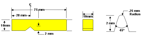
             The test uses a cantilever test piece of 10 mm X 10 mm section specimen having standard 45 ° notch 2 mm deep. This is broken by means of a swinging pendulum which is allowed to fall from a certain height to cause an impact load on the specimen. The angle rise of the pendulum after rupture of the specimen or energy to rupture the specimen is indicated on the graduated scale by a pointer. The energy required to rupture a specimen is the function of the angle of rise. Fig shows Pendulum type Impact Testing Machine.

IZOD TEST, IZOD TEST SPECIMEN
Fig shows Pendulum type Impact Testing Machine.

IZOD TEST, IMPACT FRACTURE TESTING, Pendulum type Impact Testing Machine


CHARPY TEST

               This test is more common than Izod test and it uses simply supported test piece of 10 mm X 10 mm section. The specimen is placed on supports or anvil so that the blow of striker is opposite to the notch.

CHARPY TEST, CHARPY TEST SPECIMEN

CHARPY TEST, CHARPY TEST SPECIMENCHARPY TEST, CHARPY PENDULUM IMPACT TEST, PENDULUM IMPACT TEST


The energy used in rupture the specimen in both Charpy and Izod tests is calculated as follows:

Initial energy = WH = W(R-R cos Î±) = WR (1- cos Î± )
Energy after rupture = WH1  = W(R-R cos Î²) = WR(1- cos Î²)
Energy used to rupture specimen = WH- WH1
                                                       WR (1-cos Î±) - WR (1-cos Î²)
                                                       = WR [(1-cos Î±) - (1-cos Î²) ]
                                                       = WR [cos Î² - cos Î± ]

Where, W = Weight of pendulum/strike
               H = Height of fall of center of gravity of pendulum/strike
               H1 = Height of rise of center of gravity of pendulum/strike
               Î±  = Angle of fall
               Î² = Angle of rise, and
               R = Distance from C.G of pendulum/striker to axis of rotation O.

Effect of important variables on impact strength:
  1. Angle of notch. There is no appreciable effect of notch angle until its value exceeds 60°
  2. Shape of the notch. As the sharpness of the notch increases the energy required to rupture the specimen deceases.
  3. Dimensions of the specimen. By decreasing the dimensions of the specimen the energy of rupture decreases.
  4. Velocity of Impact. The important resistance decreases above certain critical velocity, this varies from metal to metal.
  5. Specimen Temperature. The temperature of specimen for a particular metal, determines whether the failure will be brittle, ductile or mixed character.

CHARPY TEST, IMPACT FRACTURE TESTING

Saturday, 28 March 2020

HARDNESS TEST

            The hardness of material is its resistance to penetration under a localized pressure or resistance to abrasion. The hardness can be determined by any one of the following tests.

(a) Indentation (or) Penetration test:
  1. Brinell
  2. Vicker's
  3. Rockwell.

(b) Rebound test.
(c) Scratch test.

BRINELL HARDNESS TEST

This test is used: (1) to determine hardness of metallic materials, 
                             (2) to check the quality of the product,
                             (3) for uniformity of samples of metals, and 
                             (4) for uniformity of results of heat treatment.
              In this test, a standard hardened steel ball is pressed into the surface of the specimen by a gradually applied load which is maintained on the specimen for definite time. The impression so obtained is measured by a microscope and the Brinell Hardness Number (B.H.N) is found out by following equation:

B.H.N = Applied load in KG/Area of impression or indentation of steel ball in m2
             = P/A
BRINELL HARDNESS TEST, BRINELL HARDNESS TEST FORMULA


Brinell Hardness Tester: Brinell hardness tester is shown in below Fig.


BRINELL HARDNESS TEST, BRINELL HARDNESS TESTER


The hardness test is carried out as follows:
  • Place the test sample on the top of the test table and rise it with the elevating screw, till the test sample just touches the ball.
  • Apply the desired load (about 30' diameter of the ball in mm) either mechanically or by oil pressure.
  • The steel ball during this period moves to the position of the sample and makes an impression or indentation.
  • Measure the indentation diameter at two places, either on the screen provided with the machine or by coinciding the two points of a reading microscope.
  • Using above equation, one can calculate BHN after substituting the values of P, D, d.

Precautions:

(1) The Brinell test should be performed on smooth, flat specimen from which dirt and scale have been cleaned.
(2) Successive impressions made too close to one another tend to produce high readings because of workhardening.
(3) The test should not be made on the specimen so thin that the impression shows through the metal nor should impressions be made too close to the edge of a specimen.

Advantages:
  • It is widely applied in the industry due to the rapidity and simplicity with which they may be performed.
  • Due to the small size of the impression produced we can achieve high accuracy.
  • Also Rockwell hardness number can be converted to Brinell number using special table or chart.
  •  For both hard and soft material it can be used.

Disadvantages:
  1. The test machine is very heavy.
  2. The area of indentation is quite large that it affects the surface quality. This is why, some it is considered as a destructive test.
  3. The thickness of the test sample also limits its use, e.g., thin sheets will bulge or be destroyed during the test.
  4. For very hard materials, the test results are unreliable. The ball gets flattened on hard surfaces.
  5. One faces difficulty in measuring the indentation diameter accurately.

BRINELL HARDNESS TESTER
BRINELL HARDNESS TEST

VICKER'S HARDNESS TEST

This is similar to Brinell Hardness test, but in this method the drawback of the flattening of the steel ball in testing harder materials is eliminated. It uses a similar relationship and most of the errors and limitations of Brinell Hardness test are eliminated. In this method of hardness testing a diamond square based pyramid indentor with 136° angle between opposite faces is used. The load varies from 5 kg to 120 kg in increments of 5 kg. Similar to Brinell and Rockwell hardness measuring methods, this method also uses the indentation produced by the indentor (Diamond pyramid). The indentor gives geometrically similar impressions under different loads.
A piston and a dash pot of oil is used for controlling the rate and duration of loading. The specimen is placed on the anvil, which is then raised to indentor. Load is applied and then removed. The value of Vicker's Hardness can be obtained by the following relation:

VPN=DPN=


Where VPN = Vicker's Pyramid Number and
             DPN = Diamond Pyramid Number

Let P is the load applied,
       d is the average length of two diagonals, in mm, and 
       q is the angle between opposite faces of diamond pyramid (136°). Then


              This method is used for the determination of hardness of very thin and very hard materials. This method also facilitates the ease of measurement of a diagonal of the indentation area ( Fig ), as compared to circular dimensions, which are difficult to measure. This method is rapid, accurate and suitable for metals as thin as 0.15 mm. The indentor is capable of giving geometrically similar impression with different loads. Obviously, the hardness number is independent of the load applied. Some typical values of VPN are:

Material
VPN Value (Kg/mm2)


Diamond
8400
Steel
210
Aluminium
22
Lead
12
Tungsten carbide
2100


             The values of Brinell and Vickers hardness are practically the same up to 300. We must note that Vicker's test can be carried out accurately on polished surfaces but does not give accurate results when used for rough surfaces.

VICKER'S HARDNESS TEST

VICKER'S HARDNESS TEST

TORSION TEST

              The torsion test is carried out to determine the value of modulus of rigidity and ultimate shear strength of a metallic specimen. A schematic diagram of a torsion testing machine is shown in fig. The torsion test is carried out to determine the value of modulus of rigidity and ultimate shear strength of a metallic specimen. A schematic diagram of a torsion testing machine is shown in fig.

ROCKWELL HARDNESS TEST


ROCKWELL HARDNESS TEST

FATIGUE TEST

                This failure occurs as a result of repeated application of small loads (cyclic stresses) which are individually incapable of producing plastic deformation. Eventually these repeated loads cause a macro crack to open and spread across the piece. Stress intensification occurs and ultimately a sudden, brittle fracture results. The maximum stress that a material that can withstand without failure for a specific large number of cycles of stress is termed its fatigue or endurance limit. Fatigue is distinguished by 3 main features: 
                                                       (a) loss of strength
                                                       (b) loss of ductility and 
                                                       (c) increased certainty in strength and service

Fatigue failure takes place due to the following reasons: 

(1) Corrosion: Corrosion reduces the number of cycles required to reach for every stress amplitude.
(2) Surface finishsurface finish , such as tool marks  or scratches.
(3) Temperature: as a consequence of oxidation or corrosion of the metal surface increasing, increase in temperature can lead to a reduction in fatigue properties.
(4) Internal voids such as shrinkage cracks and cooling cracks in castings and weldments.
(5) Defects, stresses introduced by electroplating.
(6) stress concentration points like notches, key ways, screw threads and machining under cuts.

Fatigue Failure

One can recognize  by the appearance of fracture. Fatigue failure has a number of specific features compared with failure under static loads:
Fatigue spectrum, Fatigue test

  1. It occurs at lower stress than the failure at static load, i.e., lower than the yeild strength or ultimate strength.
  2. Failure starts on the surface (or near it) locally, in places of stress (strain) concentration. Local stress concentrations are formed by surface defects appearing on cyclic loading or notches as traces of surface treatment or the effect of the surrounding medium.
  3. Failure occurs in number of stages; accumulation of defects in the material: nucleation of fatigue cracks; gradual propagation and joining of some cracks into single main crack; and rapid final destruction.
  4. Failure has the typical structure which reflects the sequence of fatigue processes. A failure usually has the initial zone of destruction (the zone of nucleation of micro cracks), the fatigue zone, and the final failure zone (above Fig.). The initial zone of failure is usually near the surface and has small size and smooth surface. The fatigue zone is the zone where a fatigue crack gradually develops. It has typical concentric ripple lines which are an evidence of jump wise propagation of fatigue cracks. The fatigue zone develops until the increasing stresses in the gradually diminishing actual section attain a level at which instantaneous destruction takes place and forms the zone of final failure.   
    Fatigue fracture, Surface of a fatigue fracture

The main basic reasons for taking place of fatigue failures are:-
(i)-Surface imperfections like machining marks and surface irregularities.
(ii)-Stress concentrations like notches, keyways, screw threads and matching undercuts.
(iii)- At low temperature the fatigue strength is high and decreases gradually with rise temperature.
(iv) Fatigue strength reduces by corroding environments. Following surface treatments like polishing, coating, carburizing, nitriding, etc., their effect can be reduced.

Wohler’s Fatigue Test:
              Figure shows a diagrammatic sketch of Wohler fatigue testing machine. In this machine, the specimen in the form of cantilever forms the extension of a shaft which is driven by an electric motor. Through a ball bearing, dead loading is applied to the specimen. When the machine is in action i.e., it runs, the specimen rotates and the fibres of the specimen are subjected to reversed stresses. In some instances the specimen is tapered or a two point loading is applied to obtain a uniform surface stress over a considerable length of specimen.

Wohler’s Fatigue Test, FATIGUE TEST,

                To cause failure the number of cycles vary with applied stress. When stress is higher, fewer are the cycles required for causing the fracture. Obviously, a stress is reached below which fracture would not take place within the limits of a standard test and this is termed as 'endurance limit'. The length of such a standard test depends on the material being tested and types of loading. Usually it is of the order of 5,00,000 cycles for very hard steels, 50,00,000 for soft steels; 100,00,000 for cast steel and cast iron; and for non-ferrous metals and alloys from 10,00,000 to about 5,00,00,000. If the fracture does not take place within these limits, then it is understood that it will not take place at all.
                There are certain well defined characteristics for fatigue failures of metallic materials. The fractured surface frequently exhibit two distinct zones. One can find the cause of the failure by careful examination of such a failure. There is a smooth part usually showing concentric markings starting from a nucleus stress raisers, and rougher part often presenting crystal line faces.

@2017 All Rights Reserved. Designed by WWW.SMARTWAY4STUDY.COM !!!! Sitemap !!!! Blogger Templates