LATEST UPDATES

Saturday, 28 September 2024

TYPES OF LINES

TYPES OF LINES:

1) Out Lines:

          These are the most common lines used in Drawings. Lines drawn to represent visible edges, corners and surface boundaries of objects are called as Outlines (or) Principle lines. They are continues thick and solid lines.

2) Margin Lines:

          These lines are continues thick and wide lines along which the points are trimmed.

3) Dimension Lines and extension Lines:

          Dimension lines are thin, solid lines. These lines show the direction, length, and limits of the dimensions of a part. Dimension lines are drawn with an arrowhead at both ends. They are terminated at the outer ends by pointed arrowheads touching the outlines, extension lines or centre lines. A single style of arrowhead should be used throughout the drawing.

          Extension lines are also continues thin lines. Extension lines are drawn close to, but never touching, the edges or surface they limit. These are extended by  about 3 mm beyond the dimension line, length of extension lines is generally suited to the number of dimensions they limit. They should be perpendicular, or at right angles, to the dimension line. 

4) Construction lines:

          These lines are used for constructing figures. These are shown in geometrical drawings only. These are continues thin light lines.

5) Hatching or section lines:

          Section lines, also known as hatch patterns, indicate the surfaces in a sectional view as they would appear if the part were actually cut along the cutting plane line. These are continues thin lines that are normally drawn at 45-degree angle to the main outline of the section. They are uniformly spaced about 1 mm to 2 mm apart. 

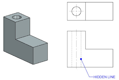
6) Leader (or) Pointer Lines:

          Leader lines is drawn to connect dimensional notes, material specifications, and process notes with the feature to which it applies. It is a continues thin, solid line with an arrowhead at one end. These are bent (or) angled at the start, but should always end horizontal at the notation. When leader lines reference a surface, a dot is used instead of an arrowhead.


7) Border Lines:

          Perfectly rectangular workspace is determined by drawing the border lines. These are continues thin lines.

8) Break Lines:

          Break lines are drawn to show that a part has been shortened to reduce its size on the drawing. In general two variations of break lines in engineering drawing, they are the long break line and the short break lines. 

          Long break lines are thin ruled lines with short zigzags within them to indicate a break.

          Short break lines are continues thick, wavy solid lines that are drawn freehand. They are drawn to show a short break, or irregular boundaries.

          When either of these break lines is used to shorten an object, you can assume that the section removed from the part is identical to the portions shown on either side of the break.

9) Hidden (or) Dotted Lines:

          Hidden lines are used to show edges and surfaces that are not visible in a view. These are also called as Dotted lines. These lines are drawn as thin, evenly spaced dashes ( 2 mm spaced and equal distances of 1 mm apart). A surface or edge that is shown in one view with an object line will be shown in another view with a hidden line. When a hidden line meets or intersects another hidden line or an outline, their point of intersection or meeting should be clearly shown.

10) Centre Lines:

          These lines are drawn to indicate the axes of cylindrical, conical or spherical objects or details, and also used to show the centre lines of circles and arcs. They are thin, long, chain lines  composed of alternatively long and dot spaced approximately 1 mm apart. Centre lines should extend for a short distance beyond the outlines to which they refer. Centre lines can also show the symmetry of an object. The point of intersection of the two centre lines must always be indicated.

11) Cutting plane lines:

          The location of the cutting plane is shown by this line. This is long, thin, chain line, thick at ends only.

12) Chain Thick:

          These lines are used to indicate special treatment of the surface.


Friday, 27 September 2024

LINES in Drawing

Various types of lines used in general engineering drawing are shown below  

Types of Lines:

Solid Lines:

          These are the most commonly used lines in Engineering Drawing. They represent the edges, surfaces, or Outlines of an object, Solid lines are typically used to depict the visible parts of an object.
Thin Lines:

          These are used for various purposes, such as dimension lines (showing the size of an object), Extension lines (extending a line on an object to aid in dimensioning), and leader lines (connecting a dimension number or note to a feature).

Dashed Lines:

Also known as hidden lines. Dashed lines are used to represent edges or surfaces that are not visible in a particular view. For example, they might show the edges of an object that are hidden behind other parts.

Dotted Lines:

          Often used for center lines or symmetry lines, dotted lines indicate the geometric centre of an object or a part. They can also be used to represent the path of movement for moving parts.

Phantom Lines:

          These are used to indicate alternate positions of a moving part or adjacent positions of related parts.

Centre Lines:

          Parts with holes and symmetrical features can be shown by using centre lines. Symmetry can reduce the number of dimensions in a drawing and make it more visually appealing, making it easier for the reader to comprehend.

Dimension Lines:

          Extension lines are used to describe the data being collected. Two arrow heads separate the extension lines on the dimension line from the measurement above (or inside, as shown in the image).

Cutting plane Lines:

          The cutting plane lines illustrate the path of the cutout in a cutout view. The A-A cutting line may be seen here bringing both types of holes into view.


Thursday, 26 September 2024

DRAWING SHEET

          Drawing sheet is the medium on which drawings are prepared by means of pencils (or) pen. Drawing Sheets are available in many types and sizes (like A4, A3, A2, A1, A0 etc.,). In general we prepare pencil-drawings, for this the paper we selected should be tough, strong and smooth surface. It's thickness should be uniform and as white as possible. When the rubber eraser is used on it, fibres should not disintegrate. Good quality of paper should be selected for drawings which are to be inked and preserved for a long time. It should be such that the ink does not spread. Thin and cheap quality paper may be used for drawings from which tracings are to be prepared.

          The Standard sizes of drawing papers: ~ recommended by the Bureau Of Indian Standards (B.I.S) are given below

While in the drawing sheet .. first we have to draw border lines and title box and then we have to start drawing

Title block:

          The document's title in an engineering drawing block is found in the bottom right-hand corner of the page. Also known as the information blocks. It includes the part name, the names of the people who worked on the part (design, checking, and approval), the name of the company, the drawing number, ad other relevant information.

          In addition, it includes technical details such as the measurement units, the angle of projection, the surface polish criteria, the scale, and the material of construction. Title blocks are used for a better understanding of all parts of technical drawing. 


Tuesday, 24 September 2024

T-Square

          A T-square (T-shaped ruler) is a tool used in hand-drawings. Generally it is made up of hard quality wood. It consists of two parts - The stock and The Blade  jointed together at right angles to each other by means of screws and pins.

          The stock is placed adjoining the working edge of the board and is made to slide on it as and when required. The blade lies on the surface of the board. Its distant edge which is generally bevelled, is used as the working edge and hence, it should be perfectly straight. The nearer edge of the blade is never used. The length of the blade is selected so as it suit the size of the drawing board. Now-a-days T-Square is also available of celluloid (or) plastic with engraved scale.

Uses:

     (i) The T-Square is used for drawing horizontal lines. The stock of the T-Square is held firmly with the left hand against the working edge of the board, and the line is drawn from left to right as shown in fir 1.3. The pencil should be held slightly inclined in the direction of the line (i.e., to the right) while the pencil point should be as close as possible to the working edge of the blade. Horizontal paralleled fines are drawn by sliding the stock to the desired positions Fig. 1-3.

     (ii) The working edge of the T-Square is also used as a base for set-squares to draw vertical, inclined or mutually parallel lines. A pencil must be rotated while drawing lines for uniform wear of lead. The T-Square should never be used on edge other than the working edge of the board. It should always be kept on the board even when not in use.


     (iii) Testing the straightness of the working edge of the T-Square: Mark any two points A and B (fig 1.4) spaced wide apart and through them, carefully draw a line with the working edge. Turn the T-Square upside down as shown by dashed lines and with the same edge, draw another line passing through the same two points. If the edge is defective the lines will not coincide. The error should be rectified by planing or sand-papering the defective edge.

DRAWING BOARD

 DRAWING BOARD:

Drawing board is rectangular in shape and is made of strips of well-seasoned soft wood about 25 mm thick. It is cleated at the back by two battens to prevent warping. One of the edges of the board is used as the working edge, on which the T-square is made to slide. It should, therefore, be perfectly straight. In some boards, this edge is grooved throughout its length and a perfectly straight ebony edge is fitted inside this groove. This provides a true and more durable guide for the T-square to slide on.

Drawing board is made in various sizes. Its selection depends upon the size of the drawing paper (like A4, A3, A2, A1, A0 etc) to be used. The sizes of drawing boards recommended by the Bureau of Indian Standards (IS:1444-1989) are tabulated in table.

 For use in schools and colleges, the last two sizes of the drawing boards are more convenient. Large-size boards are used in drawing offices of engineers and engineering firms. The drawing board is placed on the table in front of the student, with its working edge on his left side. It is more convenient if the table-top is sloping downwards towards the student. If such a table is not available, the necessary slope can be obtained by placing a suitable block of wood under the distant longer edge of the board.


Friday, 13 September 2024

DRAWING INSTRUMENTS AND THEIR USES

Drawing instruments are used to prepare drawings easily, quickly and accurately. The quality of the instruments has a big impact on how accurate the drawings are. With instruments of good quality, desirable accuracy can be attained with ease. It is, therefore, essential to procure instruments of as superior quality as possible.

Below is the list of minimum drawing instruments and other drawing materials which every student must possess:

1 . Drawing board

2. T-square

3.  Set-squares - 45° and 30°- 60°

4.  Drawing instrument box, containing: (i) Large-size compass with inter-changeable pencil and pen legs (ii) Lengthening bar (iii) Small bow compass (iv) Large-size divider (v) Small bow divider (vi) Small bow ink-pen (vii) Inking pen

5.  Scales

6.  Protractor

7.  French curves

8.  Drawing papers

9.  Drawing pencils

10. Sand-paper block

11. Eraser (Rubber)

12. Drawing pins, clips or adhesive tapes

13. Duster

14. Drafting machine

15. Roll-n-draw.

We shall now describe each of the above in details with their uses:


Wednesday, 4 September 2024

TO CONSTRUCT SQARES

A) By using Ruler and set square:

 1. Using a ruler or T-Square, draw a line segment AB corresponding to the length of one side of the square.

2. Place the set square at one end of the line segment (i.e., A) and draw a perpendicular line that is longer than the side of the square.

3. Using the ruler, mark a point on this line that corresponds to the length of the side of the square.

4. Place the set square at another end of the line segment (i.e., B) and draw a perpendicular line that is longer than the side of the square.

5. Using the ruler, mark a point on this line that corresponds to the length of the side of the square.

6. Using the ruler, connect the two marks made in steps 3 and 5 to form the square.


B) By using T-square and set square:

1. Using a ruler or T-Square, draw a line segment AB corresponding to the length of one side.

2. At A and B draw verticals AE and BF

3.  From point A draw a line  inclined at 45 to AB, Cutting line BF at C.

4.  From point B draw a line  inclined at 45 to AB, Cutting line AE at D.

5. Draw a line connecting C and D.

6. Then ABCD is the required square.

C) By using compass:

1. Draw a line segment AB corresponding to the length of one side.

2. At A, draw a line AE perpendicular to AB.

3. With centre A, and radius AB, draw an arc cutting AE a D.

4. With centre B, and radius AB, draw an arc.

5. With centre D, and same radius draw an arc cutting previously draw arc from B.

6. Mark the intersecting point as C.

7. Draw lines C with B, C with D.

8. Then ABCD is the required square.


@2017 All Rights Reserved. Designed by WWW.SMARTWAY4STUDY.COM !!!! Sitemap !!!! Blogger Templates