LATEST UPDATES

Friday, 18 November 2016

Natural Frequency of Free Transverse Vibrations Due to Uniformly Distributed Load Acting Over a Simply Supported Shaft

          Consider a shaft AB carrying a uniformly distributed load of 'w' per unit length as shown in Fig., 
Let           y1 = Static deflection at the middle of the shaft, 
                a= Amplitude of vibration at the middle of the shaft, and 
          w= Uniformly distributed load per unit static deflection at the middle of the shaft = w/y1 . 

          Now consider a small section of the shaft at a distance 'x' from A and length 'δ x'.
Let        y = Static deflection at a distance 'x' from A, and length 'δ x'
              a = Amplitude of its vibration.
          ∴ Work done on this small section
          Since the maximum potential energy at the extreme position is equal to the amount of work done to move the beam from the mean position to one of its extreme position therefore
          Maximum potential energy at the extreme position
          Assuming that the shape of the curve of a vibrating shaft is similar to the static deflection curve of a beam, therefore
          Substituting those values in equation (i), we have maximum potential energy at the extreme position
          Since the maximum velocity at the mean position is 'ω.a1', where 'ω'  is the circular frequency of vibration, therefore
          Maximum kinetic energy at the mean position
          We know that the maximum potential energy at the extreme position is equal to the maximum kinetic energy at the mean position, therefore equating equations (iiand (iii),
          When the shaft is simply supported, then the static deflection at a distance 'x' from A is 
Where          W = Uniformly distributed load per unit length,
                       E = Young's modulus or the material o the shaft, and
                       I = Moment o inertia of the shaft.
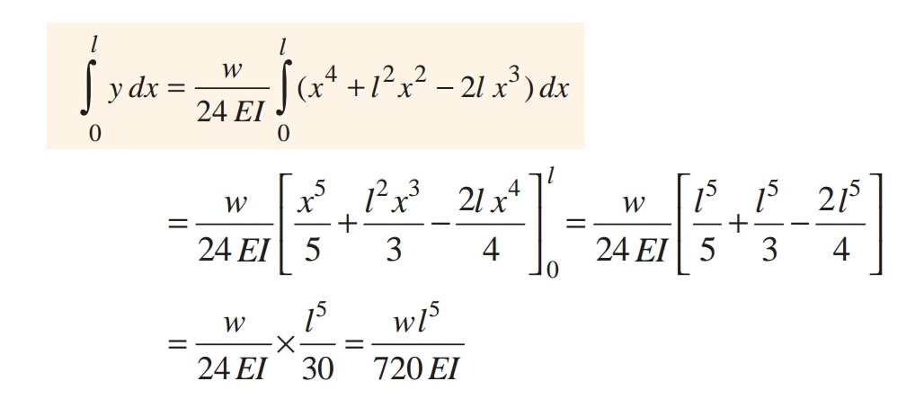
          Now integrating the above equation (v) within the limits 0 to l, 
          Substituting the value in equation (ivfrom equation (vi) and (vii), we get circular frequency due to uniformly distributed load, 
   Natural frequency due to uniformly distributed load, 
          We know that the static defection of a simply supported shaft due to uniformly distributed load of  'w' per unit length, is
Equation (ixmay be written as,

Thursday, 17 November 2016

Natural Frequency of Free Transverse Vibrations of a Shaft Fixed at Both Ends Carrying a Uniformly Distributed Load

          Consider a shaft AB fixed at both ends and carrying a uniformly distributed load 'w' per unit length as shown in Fig.,
    We know that the static deflection at a distance 'x' from A is given by
Integrating the above equation on both sides  with limits from 0 to l, 
Now integrating  y2  within the limits from 0 to l, 
We know that
and natural frequency,
Since the static deflection of a shaft fixed at both ends and carrying a uniformly distributed load is


Natural Frequency of Free Transverse Vibrations For a Shaft Subjected to a Number of Point Loads

           Consider a shaft AB of negligible mass loaded with point loads W1 , W2,  Wand W4 etc., as shown in Fig (a)., Let mmm3 and metc., be the corresponding masses in Kg. The natural frequency of such a shaft may be found out by the following two methods: 

1. Energy (or Rayleigh’s) method

          Let y, y, y3 and yetc. be total deflection under loads W1 , W2W and W4 etc., as shown in Fig (a).,
          We know that maximum potencial energy 
and maximum kinetic energy
          Equating the maximum potencial energy and maximum kinetic energy we have, 
          Natural frequency of transverse vibration

2. Dunkerley’s method

          The natural frequency of transverse vibration for a shaft carrying a number of point loads and uniformly distributed from Dunkerley's empirical formula. According to this

Where          fn = Natural frequency o transverse vibration of the shaft carrying point loads and uniformly distributed load.
                   fn1 , fn2 fn3 etc., = Natural frequency of transverse vibration of each point load.
                     fns = Natural frequency of transverse vibration off the uniformly distributed load (or due to the mass of the shaft).

          Now consider a shaft AB loaded as shown in Fig (b).,

Let δ1 δδetc., = Static deflection due to the load W1 , W2W etc., when considered seperately
                       δS = Static deflection due to the uniformly distributed load or due to the mass of the shaft.

We know that natural frequency of transverse vibration due to the load W1 ,
Similarly, natural frequency of transverse vibration due to the load W2 ,
and, natural frequency of transverse vibration due to the load W3 ,
Also natural frequency of transverse vibration due to uniformly distributed load or weight of the shaft, 
Therefore, according to Dunkerly's empirical formula, the natural frequency of the whole system, 

Note: 1. When there is no uniformly distributed load or mass of the shaft is negligible, then δS  = 0.
 2. The value of etc., for a simply supported shaft may be obtained from the relation 

Where    δ= Static deflection due to load W, 
      a and b = Distance of the load from the ends,
                 E = Young's modulus for the material of the shaft,
                 I = Moment of inertia of the shaft, and
                 l = Total length of the shaft.

Friday, 11 November 2016

Critical or Whirling Speed or Whipping Speed of a Shaft


Critical Speed: "Critical or whirling or whipping speed is the speed at which the shaft tends to vibrate violently in transverse direction".
(or)
"The speed at which the shaft runs so that the additional deflection of the shaft from the axis of rotation becomes infinite, is known as Critical or Whirling speed".
          In actual practice, a rotating shaft carries different mountings and accessories in the form of gears, pulleys etc., When the gears or pulleys are put on the shaft, the centre of gravity of the pulley or gear does not coincide with the centre line of the bearings or with the axis of the shaft, when the shaft is stationary. This means that the centre of gravity of the pulley or gear is at a certain distance from the axis of rotation and due to this, the shaft is subjected to centrifugal force. This force will bent the shaft, which will further increase the distance of centre of gravity of the pulley or gear from the axis of rotation. This correspondingly increases the value of centrifugal force, which further increases the distance of centre of gravity from the axis of rotation. This effect is cumulative and ultimately the shaft fails. The bending of shaft not only depends upon the value o eccentricity (distance between centre of gravity of the pulley and the axis of rotation) but also depend upon the speed at which the shaft rotates.

The critical speed essentially depends on
          1. The eccentricity of the C.G of the rotating masses from the axis of rotation of the shaft 
          2. Diameter of the disc.
          3. Span (Length) of the shaft, and 
          4. Types of support connections at its end.

"The speed at which the shaft runs so that the additional deflection of the shaft from the axis of rotation becomes infinite, is known as Critical or Whirling speed".
          Consider a shaft of negligible mass carrying a rotor, as shown in Fig (a)., The point 'O' is on the shaft axis and 'G' is the centre of gravity of the rotor. When the shaft is stationary, the centre line of the bearing and the axis of the shaft coincides.  Fig (b) shows the shaft when rotating about the axis of rotation at a uniform speed of 'ω' rad/s.

Let            m = Mass of the rotor,
                e = Initial distance of centre of gravity of the rotor form the centre line of the bearing or shaft axis, when the shaft is stationary.
               y =  Additional deflection of centre of gravity of the rotor when the shaft starts rotating at 'ω' rad/s.
                 s = Stiffness of the shaft i.e. the load required per unit deflection of the shaft.

Since the shaft is rotating at 'ω' rad/s , therefore centrifugal force acting radially outwards through 'G' causing the shaft to deflect is given by 
               FC = m. ω2 ( y + e)
The shaft behaves like a spring. therefore the force resisting the deflection 'y',
               = s.y
For the equilibrium position, 
          A little consideration will show that when ω>ωn, the value of 'y' will be negative and the shaft deflects is the opposite direction as shown in Fig (b).
          In order to have the value of 'y' always positive, both plus and minus signs are taken.
          We see from the above expression that when ω= ωc , the value of 'y' becomes infinite, therefore  'ωc' is the whirling speed.
          Hence the critical or whirling speed is the same as the natural frequency of transverse but its will be revolutions per second.

Note:

1. When the centre of gravity of the rotor lies between the centre line o the shaft and the centre line of the bearing, 'e' is taken as negetive. On the other hand, if the centre of gravity of the rotor does not lie between the centre line of the shaft and the centre line of the bearing (as in the above article) the value of e is taken positive.
2. To determine the critical speed of a shaft which may be subjected to point loads, uniformly distributed load or combination of both, find the frequency of transverse vibration which is equal to critical speed of a shaft in r.p.s. The Dunkerley's method may be used for calculating the frequency.
3. A shaft supported is short bearings (or ball bearings) is assumed to be a simply supported shaft while the shaft supported in long bearing (or journal bearing) is assumed to have both ends fixed.
@2017 All Rights Reserved. Designed by WWW.SMARTWAY4STUDY.COM !!!! Sitemap !!!! Blogger Templates