A little consideration will show that when an unbalanced machine is installed on the foundation, it produces vibration in the foundation (supporting structure). These transmitted forces in most instances produce undesirable effects such as noise. In order to prevent these vibrations or to minimise the transmission of force to the foundation, the machines are mounted on springs or dampers or some vibration isolating material, as shown in Fig., The arrangement is assumed to have one degree of freedom, i.e., it can move up and down only.
An isolation system attempts either to prevent a delicate object from excessive vibration transmitted to it from its supporting structure or to prevent vibratory forces generated by machines from being transmitted to its surroundings. In order to reduce the force transmitted to the support structure, a proper election of the stiffness and damping coefficients must be made.
It may be noted that when a periodic (i.e simple harmonic) disturbing force F cos ωt is applied to a machine of mass 'm' supported by a spring of stiffness 'S', then the force is transmitted by means of the spring and the damper or dashpot to the fixed support or foundation.
The ratio of the force transmitted (FT) to the force applied (F) is known as the isolation factor or transmissibility ratio of the spring support.
We have discussed above that the force transmitted to the foundation consists of the following two forces:
- Spring force or elastic force which is equal to s. xmax and
- Damping force which is equal to c. ω .xmax.
Since these two forces are perpendicular to one another, as shown in Fig., therefore transmitted,
Transmissibility ratio,
We know that
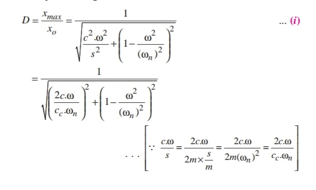
We have seen previously that the magnification factor,
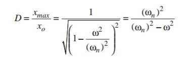
When the damper is not provided, then c=0, and
From, above, we see that when ω/ωn>1, ε is negative. This means that there is a phase difference of 180° between the transmitted force and the disturbing force (F cos ωt ). The value of ω/ωn must be greater than √2 if ε is to be less than 1 and it is the numerical value of , independent of any phase difference between the forces that may exist which is important. It is therefore more convenient to use equation in the following form, i.e.,
Below Fig. shows the graph for different values of damping factor C/Cc to show the variation of transmissibility ratio (ii) against the ratio ω/ωn.
- When ω/ωn= √2 , then all the curves pass through the point ε=1 for all values of damping factor C/Cc .
- When ω/ωn < √2 , then ε > 1 for all values of damping factor C/Cc . This means that the force transmitted to the foundation through elastic support is greater than the force applied.
- When ω/ωn > √2 , then ε < 1 for all values of damping factor C/Cc . This means that the force transmitted through elastic support is less than the applied force. Thus vibration isolation is possible only in the range of ω/ωn > √2.
We also see from the curves in Fig. that the damping is determined beyond ω/ωn > √2 and advantageous only in the region . It is thus concluded that for the vibration isolation, dampers need not to be provided but in order to limit resonance amplitude, stops may be provided.